

Background Information
Weight Classification Systems
In accordance with Archimedes Principle the weight of all the components, crew, effects, and other loads on a vessel is equal to the weight of the volume of water that the vessel displaces. In order to be able track weight growth, as well as assist in cost estimating, and predicting the estimated weights for new designs, all the individual components on a ship are categorized into groups based on the function of that component. In the US for modern naval vessels, a system called the Extended Ship Work Breakdown Structure (ESWBS) is currently used. ESWBS is an extension of the previously used Ship Work Breakdown Structure (SWBS) and for what I am considering here they are pretty much the same.
Prior to the mid 1960s (or so) though, a different system, called the Bureau of Ships Consolidated Index (BSCI) was used. Although this system is in general similar to the SWBS/ESWBS system, there are some differences between how some specific items are categorized.
Additionally, overseas there are other, nationally based systems, including a system used in the UK based on their Naval Engineering Standards (NES). As with the BSCI system this system is in general similar to SWBS/ESWBS, however here are some differences between how some weights are categorized.
For the most part I believe that most of the data I have collected is based on either the SWBS/ESWBS or the BSCI system (depending on the date that the vessels were designed/built) however, I am pretty certain that a couple of the data points I have collected are in the UK NES system. At some point in time I hope to go back and clarify which data points are based on which system, but for now I believe that there is currently a mixture of the different systems represented.
Overall, all three systems tend to break ship weights into the following categories:
- Group 100 - Structural weights
- Group 200 - Propulsion system weights
- Group 300 - Electrical system weights
- Group 400 - Command, Communications, Computers, Controls, Intelligence, Surveillance, & Radars (C4ISR)
- Group 500 - Auxiliary systems
- Group 600 - Outfit & Furnishings
- Group 700 - Weapon systems
- Group F - Loads (which is identified as Group 800 in the NES system - I believe)
- Group M - Margins
In general, groups 100 to 700 add up to give the vessel's basic light ship weight, though for early stage designs a number of margins (from Group M) are often added to address the uncertainty in early stage design numbers. Also, if ballast is required it is often added in as well.
Light ship weight plus loads (such as crew & their effects, fuel, stores, and munitions, etc) add up to give the vessel's full load displacement.
Finally, since it is realized that over the life of a vessel it will probably grow in weight, due to added systems, ship alterations, and other various additions, typically a service life allowance is also included to reflect the allowable expected growth of the vessel. As such, the full load displacement of the vessel when new (at delivery) plus its service life allowance would be equal to the vessel's full load displacement at the end of its service life. I believe that for non-US vessels some of the terminology will be different (ie that may not call all the weights, margins, and allowances exactly the same) but I believe, in general, the overall concepts are similar.
Further details of the ESWBS/SWBS, BSCI, and NES systems can be found on the following page.
Resistance & Powering
ResistanceResistance Components - As a ship moves through the water it creates a drag force, or resistance. In general this resistance consists of several major parts, and some additional minor components. Specifically, there is;
- the frictional resistance generated by the contact of the hull's surface with the water,
- a wavemaking resistance generated by the hull as it pushes the water aside as it passes,
- a wind resistance caused by the above water portion of the vessel as it interacts with the air,
- the resistance of the appendages on the hull below the water, including such things as rudders, propeller shafts and brackets, as well as potentially other items like bilge keels, sonar domes, stabilizers, bow bulbs, and stern flaps,
- added resistance in waves, and
- other items such as wave breaking resistance, spray resistance, and an added resistance caused by the control surfaces (such as the rudders) as the ship makes minor steering c orrections in an effort to maintain its course and added resistance due to hull roughness and fouling.
Resistance Estimating Techniques - If data exists on a similar ship it is sometimes possible to use that data for estimating the resistance of a new design. However, if the new design is significantly different from the existing design this may not be fully adequate. Additionally, over the years work has been ongoing in trying to develop mathematical means of estimating a ship's resistance by modeling the ship's hull in a computer and using Computational Fluid Dynamics (CFD) methods. However, this is somewhat time consuming and not well suited to early stage estimation, where full details of a ship's hullform may not yet be fully worked out. Similarly, it is possible to build a scale model of a design and measure its resistance in a tow tank, however, this is also costly and time consuming and typically is not done till later in a design when more details on its hullform have been set. As such, several method's have been developed over the years to estimate a ship's resistance either from data on other similar ships and/or concepts that have been developed previously or through the use of model test data on Systematic Series of similar notional hullforms.
Systematic Series - In general a Systematic Series is a series of similar hullforms which have been developed and model tested. These models typically have certain major characteristics varied over the family of hulls, such as block coefficient, LCB location, and L/B ratio, etc. The model test resistance data is collected and analyzed and presented in such a way as to allow a user to interpolate an estimate of the resistance of his vessel, at its given block coefficient, LCB location, and L/B ratio, etc from the range of data provided. Some of the more common typical Systematic Series that have been developed include;
- The Taylor Standard Series -
- Series 60 - Methodical Experiments With Models Of Single-Screw Merchant Ships
- Series 62 -
- Series 64 -
- Series 65 -
- The BSRA Series -
- The SSPA Series -
- The National Physical Laboratory (NPL) Series -
- The Marwood and Bailey -
- The Webb Trawler Series -
- The NTUA Series -
- The Naval Acadmey Hydrodynamics Lab Series -
- etc
One
potential problem with using Systematic Series
though, is that they are only useful over a limited range of vessel
parameters investigated and may not cover the hullform shape or other
hullform parameters of the design that you are interested in. In
order to account for this it is sometimes possible to combine the use a
Systematic Series with data on existing vessels. I believe that
in the US Navy a method like this was used for many years, where
restance data on existing vessels or designs were compared to the
estimated resistance for those vessels as determined by the Taylor
Standard Series . The ratio of actual resistance to
estimated resistance was then plotted over a range of speeds to develop
a "Worm Curve" factor for that vessel. If you then
had a ship some what similar to an existing design, but for which some
parameter, or group of parameters, were different (such as block
coefficient or LCB, etc) you could then use the Systematic Series
to make a preliminary estimate of resistance but then multiply those
results by the Worm Curve factor for the similar
ship to adjust the results to account for differences between your
design and the hullform of the vessels in the Systematic Series.
Mathematical Regression Methods
- In more recent years alot of effort has been made into using
mathematical regression methods to condense this data down into
relatively simple mathematical terms to ease in the estimation of early
stage resistance estimation. These methods easily lend themselves to
use in spreadsheets or simple BASIC or FORTRAN programs.
Additionally, more recently some individuals and research
establishments have also made an effort at combining the data from
several Systematic Series together sometimes including
data for other specific designs or vessels for which model test or full
scale data was available. One of the most well known of this type
approach is the Netherlands Shipbuidling Model Basin's (NSMB)
mathematical method, which is also known by the name of its two
principal authors Holtrop & Mennen.
The NSMB/Holtrop & Mennen method is very powerful
and useful because it incorporates data from a wide range of hullform
types, but it is not always clear whether in doing so, if it is as
accurate for a given hull type as a method that only addresses that
specific hull type. For this reason, on this site right now I have
decided to make use of data developed by Sui Fung specifically for
transom hull ships representative of most typical modern frigate and
destroyer type hulls, instead.
Resistance Scaling
- Because many resistance estimating routines are based in part on
model tests, it is important to understand how model test resistance is
scaled when trying to estimate the full scale resistance of a ship.
For starters, it was discovered long ago that the wave pattern that a
ship generates as it moves through the water is impacted greatly by the
speed that the vessel is going in relation to the length of the
vessel. If a vessel is moving at a speed where the the waves
generated result in the bow and stern resting on peaks of the waves
then the ship will be at near even trim which is good for minimizing
resistance. However, if a vessel is moving at a speed where the
bow is at a peak but the stern is in the trough of a wave then the ship
will be operating at a greater than normal trim and the ship's
resistance will be adversely impacted. As such, the humps and
hollows in the waves generated by the ship as it moves through the
water can result in reltive increases and decreases or "humps"
and "hollows" in the ship's resistance curve,
as shown below.
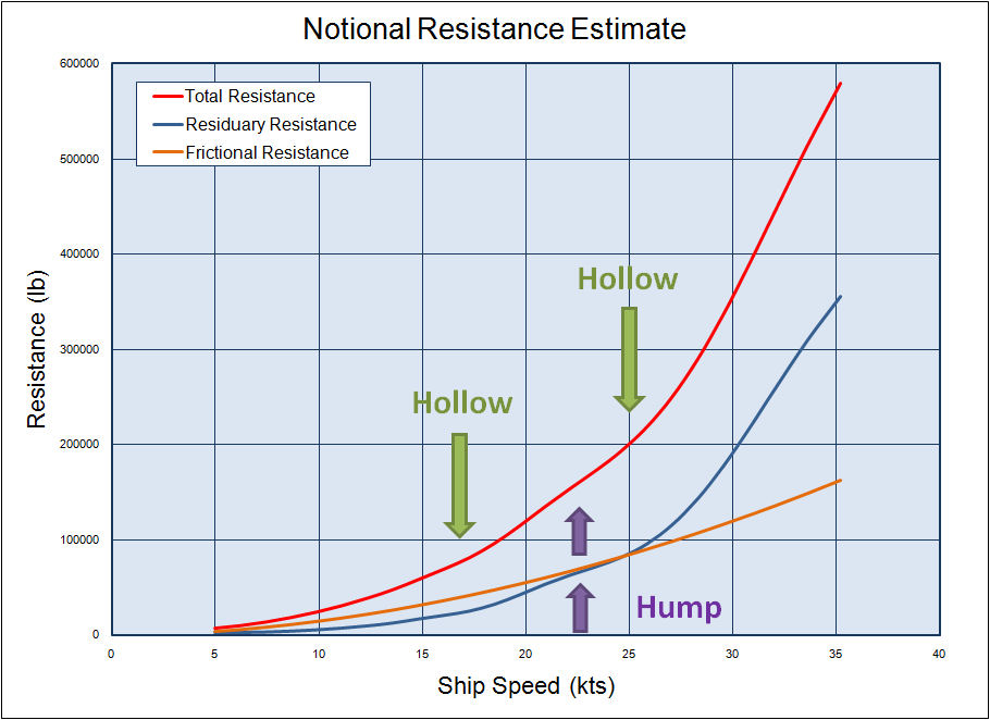
Here the
Red curve shows the
estimated total resistance while the two
major components of total resistance, the residuary
and frictional resistance are shown in Blue and Orange
respectively. As can be seen in this figure the frictional
resistance increases smoothly as speed increases, but there are humps
(as denoted by the Purple
arrows) and hollows (as denoted by the Green
arrows) in the residuary resistance curves, which also are
apparent in the overall total resistance curve.
The term Froude Number (Fn)
has been defined as a means of reporting a ship's speed in relation to
its length in a non-dimensional fashion. Specifically;
Fn = v /
sqrt (g * L)
Where;
v =
the vessel's speed
L = the vessels length
g = the acceleration due to
gravity
(all in consistant units)
In general the wave pattern generated by a
model at a given Froude number will be the same as the
wave pattern generated by the full scale ship at that same Froude
number. As such, wavemaking resistance is said to follow Froude
scaling rules. Additionally Model Scale Ratio is
defined as the ratio of the length of the full-scale ship in comparison
to the length of the model and is sometimes called l.
A s such the actual speed that a model will be operating at to give the
same Froude number as a full-scale ship will be equal to
the speed of the full-scale ship divided by the square root of the Model
Scale Ratio (eg Vm = Vs / sqrt(l)).
However, because of the viscous properties of water it is not possible
to scale all of a ship's resistance directly from a scale model, as the
frictional components of resistance do not follow the same Froude
scaling rules. For frictional resistance a different
non-dimensionalization of the vessel's speed is more significant.
This is called the Reynold's number (Rn)
and is is defined as;
Rn = v L / n
Where;
v =
the vessel's speed
L = the vessel's length
n =
the kinematic visosity of water
(all in consistant units)
Based on the size and wetted surface of the model, an estimate of the
frictional (or in some cases viscous) resistance of the model is made
based on a standard formulation. In the US many early model tests
and systematic series used a formulation put forward by the American
Towing Tank Conference (ATTC) based on
observations of measured frictional resistance of flat plates.
Here (I believe) an equation for a non-dimensional frictional
resistance coefficient (Cf) was derived as;
0.242*sqrt(Cf) = log10 (Rn *Cf)
Because the frictional resistance of a vessel
is a function of the vessel's Reynold's number,
Frictional Resistance is said to follow Reynold's number scaling
and if a model were run at a the same Reynold's number
as the full scale ship then they would have the same
non-dimensionalized Frictional Resistance coefficients, however the Froude
number's would be different and hence the wave patterns
developed by the model and full scale ship would be different, which is
why the Frictional resistance and residuary resistance components are
treated separately.
Later in 1957 the International Towing Tank Conference (ITTC)
agreed on a newer formulation for calculating a Frictional Resistance
coefficient as follows;
Cf = 0.075/(log10 (Rn) - 2)2
I believe that is this Frictional Resistance Coefficient that is used
by most (though not all) of the Systematic Series
identified above.
More recently the ITTC put forward a revised methodology
in 1978 where, instead of just considering frictional resistance based
on data for flat plates, an effort was made to account for the form of
the ship, as well. In this 1978 formulation a vessel's viscous
drag was defined as being equal to the the vessel's frictional
resistance times a (1+k) term to account for the impact
of hull curvature and form. I believe that the NSMB/Holtrop
& Mennen equations are based on this newer methodology.
As such, when scaling model test data for conventional displacement
hulls it is typical to measure the total resistance and convert it into
terms of a non-dimensional frictional resistance coefficient. For
each data point collected the calculated frictional resistance
coefficient at that speed is then subtracted from the total resistance
coefficient giving a "residuary" resistance coefficient which more or
less includes all the other factors like wave making, wave breaking,
and wave spray (if significant), etc. This is the portion of the
model test data that gets scaled to full scale by Froude scaling.
An estimate of the frictional resistance of the full-scale ship is then
added onto the residuary resistance estimate (using a similar method as
used for estimating the frictional resistance of the model), and then
additions are also made for any other additional components (such as
wind and appendage resistance).
Because
most models do not include all of the "above water" components of a
ship, the wind resistance of a ship is something that is typically
added in later based on approximation equations or if available wind
tunnel data for the ship. However, depending on the towing tank
and their standard procedures, sometimes there may be a correction to
the model-scale data to account for the wind resistance of the limited
portion of the above water hull that was included in the model tests.
Additionally, sometimes models are tested
with small scale appendages (especially for fixed components, like
bulbs etc). However, since of scaling issues with items like
rudders, fins, and bilge keels, etc, it is not uncommon that these are
not included on the model (for resistance estimating) and that an
approximation of their effects are considered later based on equations
derived for the specific component type or simply by adding in an
allowance based on previous experience.
Finally, typically an additional Correlation Allowance,
based on the size of the full scale ship and its likely surface
roughness, is typically also added in.
Appendage Drag - There are several methods of estimating appendage drag for a vessel. The book "Principles of Naval Architecture" (Ref B-1) gives information on a couple of these methods.
Specifically, the book provides several equations relating the resistance of certain specific appendage types to the geometry of these items. This includes equations specifically for;
- Bilge Keels
- Control Surfaces (such as rudders, shaft brackets, and stabilizer fins, etc)
- Shafts & Bossings, and
- Skegs
An alternate method to using these type of shape specific equations is instead to estimate the area of the appendages and multiply the area for each by an Effective Form Factor of the appendages (k2). From this a total Effective Form Factor for the ship is calculated taking into the account the surface area and k2 of each of the appendages using the ITTC 1978 viscous resistance curves. This type method is incorporated into the NSMB/H&M resistance estimation equations.
A third method is one outlined in the US Navy's Design Data Sheet 051-1 (DDS 051-1) entitled "Prediction of Smooth-Water Powering Performance for Surface-Displacement Ships" (Ref B-2). In this method, curve fits through data on exisitng vessels are provided to allow the user to make an initial estimate of appendage r esistance for a given ship.
For early stage desgin, the first two type methods noted above can be a little cumbersome in that they require the user to estimate the size of all the appendages. As such, for early stage design I have made use of the method outline in DDS 051-1.
Wind Resistance & Still Air Drag - As a ship moves through the water it encounters resistance to this motion not only from the water it is moving through, but also the air that the portion of the ship above the waterline comes in contact with. This air resistance can be considered in three ways;
- you can consider only the still air drag generated solely from the ship's forward motion (condition 1),
- you can consider the still air drag generated from the ship's forward motion plus a certain amount of head wind acting on the front of the vessel (condition 2), or
- you can consider the total air resistance of the ship taking into account any existing wind and the relative motion of the ship (condition 3).
In the first case, still air drag is the resistance that is generated by the ship assuming that there is no wind blowing other than the wind the ship is generating itself as it moves forward. Thus in this case the speed of the self generated wind is equal to the speed of the ship, and it can be considered acting only on the frontal area of the ship.
In the second case you simply add a set amount of wind speed to the ship's speed, and assume that this acts on the frontal area of the vessel. The final case however, is more complex and takes into account the relative direction of the wind to the ship as the ship moves through the water and acts on both the frontal and side areas of the ship. It would be important to calculate for estimating actual vessel performance, but for design purposes, either assuming only still air drag, or still air drag plus a certain amount of head wind is (I believe) most typical.
The book "Principles of Naval Architecture" (Ref B-1) gives several different methods for estimating Wind Resistance & Still Air Drag. These are typically of the form;
Raa = coefficient * ½ r * AT V2
Where;
- Raa = The total added air resistance
- coefficient = an empirically derived coefficient
- r = the density of the air
- AT = the frontal area of the ship above the waterline
- V = the total wind velocity (for condition 1 this would be equal to the forward speed of the ship, but in condition 2 this would include both the speed of the ship and any additional head wind)
Ref B-1 notes that in 1943 RADM D.W. Taylor derived a simplifaction to the above equation for ordinary ships where;
Raa = 0.783 * ½ * B2 VR2
Where;
- Raa = The total added air resistance
- B = the Beam of the ship (in meters)
- VR = the apparent relative wind velocity (for condition 1 this would be equal to the forward speed of the ship, but in condition 2 this would include both the speed of the ship and any additional head wind) (in meters per second)
This version of the equation is convenient for early stage design use as it doesn't require an estimate of frontal area, which may not be fully known in early stage design.
Powering
Once the resistance of a ship is estimated it is then necessary to make
an estimate of the powering requirements for the ship. In very
basic terms if you multiply the resistance of a vessel times its speed
(and make any necessary corrections for units) you get what is called
the vessel's Effective Power requirement (or EHP
for Effective Horsepower). If there were no efficiency losses or
need for margins an engine capable of producing an amount of power
equal to a ship's EHP would be able to propel the ship
at the speed for which the EHP was calculated. However,
there are many different efficiencies and margins that must be
considered which drive the total installed power requirement for a
vessel up to a value sometimes approaching twice the value of the
calculated EHP at design speed.
Hull Form
Effects
One of the first things that must be considered in determining full
power requirements is the effect of the hull on the water around
it. In addition to the drag already considered in the resistance
estimate, there are other factors that must be considered.
Amongst these are three terms called;
- wake fraction
- thrust deduction, and
- relative rotative efficiency
Wake Fraction
- as a ship moves through the water, the viscosity of the water will
result in a layer of the water near the vessel being dragged more or
less along with the ship. This results in the flow into a ship's
propellers being overall typically a little less than the speed that
the ship is traveling at, and depending on the level of detail that you
are going into for your resistance and powering estimates it may become
necessary to try and estimate this. For early stage design this
is trypically done using curve fits or rules of thumb based on data on
similar ships.
Thrust Deduction -
similar to wake fraction, there is also a term called the thrust
deduction factor. In simple terms, the total thrust that a
propeller (or group of propellers) must produce to propel a ship tends
to be a little more than the total resistance of the ship. This
differnce is sometimes called an augment of resistance or reduction in
thrust available at the propeller. According to the book
"Resistance and Propulsion of Ships" (Ref B-3) it is caused by a number
of factors including the propeller accelerating the water into the
stern which can cause an increase in frictional resistance, influences
of the potential-velocity field in which the propeller operates and
possible influences that the propeller may have on the stern wave
pattern of the ship. For our purposes its enough just to know
that the total thrust required to be produced by the propellers is
going to be a little more than the estimated resistance, and like the
wake fraction, in early stage design it is usually estimated by means
of using curve fits or rules of thumb based on data on similar ships.
Relative
Rotative Efficiency -
Propeller Efficiency -
Shaft
and Mechanical Efficiency -
Weight Classification Systems (please see the Background page for more details)
SWBS - The US Navy's Ship Work Breakdown Structure. It is a method for categorizing the weights of all components of a vessel into groups based on the function .
ESWBS - The US Navy's Extended Ship Work Breakdown Structure. ESWBS is an extension of the previously used Ship Work Breakdown Structure (SWBS) and for our purposes they are pretty much the same.
BSCI - The US Navy's Bureau of Ships Consolidated Index. Prior to the mid 1960s (or so) this system was used for categorizing weights. Although this system is in general similar to the SWBS/ESWBS system, there are some differences between how some weights are categorized.
NES - A system used in the UK based on their Naval Engineering Standards (NES). As with BSCI the NES system is in general similar to the SWBS/ESWBS system, however there are some differences between how some weights are categorized.
Weight Categories (please see the Background page for more details)
Group 100 - In all the weight classification methods noted above, group 100 generally refers to all components of the ship relating to the basic structure of the vessel. It includes items such as:
- hull plating,
- deck structure, and
- bulkheads, etc.
- paint,
- insulation,
- furniture, or
- handling gear (like cranes, windlasses, etc)
Group 200 - In all the weight classification methods noted above, group 200 generally refers to all components of the ship relating to the vessel's propulsion system. It includes items such as:
- main propulsion engines,
- gearing,
- shafting,
- propellors, and
- fuel oil & lube oil service systems, etc.
- air conditioning & ventilation,
- the ship's distilling plant, or
- the ship's fuel oil and lube oil transfer systems (ie the system used to transfer the fuel and lube oil from their storage tanks to their ready service tanks)
I may also refer to this as SWBS200 or w200. In general I had intended both group 200 and SWBS 200 were meant to refer to the category and w200 is intended to actually refer to the weight of the items in this category. Eventually I intend to go back and try to ensure that I have been consistent, as I get the time. Similarly v200 will refer to the vertical height of the center of the weight of the group 200 items and c200 will refer to the estimated cost of those items.
Group 300 - In all the weight classification methods noted above, group 300 generally refers to all components of the ship relating to the vessel's electrical generation and distribution systems. It includes items such as:
- the ship service generators,
- the emergency generator,
- lighting distribution (cabling),
- power distribution (cabling), and
- lighting fixtures, etc.
- electronics (like radars, sonars, satellite communications, & radars, etc), or
- controls, etc
I may also refer to this as SWBS300 or w300. In general I had intended both group 300 and SWBS 300 were meant to refer to the category and w300 is intended to actually refer to the weight of the items in this category. Eventually I intend to go back and try to ensure that I have been consistent, as I get the time. Similarly v300 will refer to the vertical height of the center of the weight of the group 300 items and c300 will refer to the estimated cost of those items.
Group 400 - In all the weight classification methods noted above, group 400 generally refers to all components of the ship relating to the vessel's Command, Communications, Computers, Controls, Intelligence, Surveillance, & Radars (C4ISR) systems. It includes items such as:
- the navigation system,
- internal communications,
- external communications,
- the degaussing system, and
- combat related electronics (like radars, sonars, etc)
I may also refer to this as SWBS400 or w400. In general I had intended both group 400 and SWBS 400 were meant to refer to the category and w400 is intended to actually refer to the weight of the items in this category. Eventually I intend to go back and try to ensure that I have been consistent, as I get the time. Similarly v400 will refer to the vertical height of the center of the weight of the group 400 items and c400 will refer to the estimated cost of those items.
Group 500 - In all the weight classification methods noted above, group 500 generally refers to all components of the ship relating to the vessel's auxiliary systems. It includes items such as:
- heating,
- ventilation,
- air conditioning,
- ballasting systems (but not the actual ballast water), and
- fuel and lube oil transfer systems,
- the distilling plant, and
- fire fighting systems, etc.
I may also refer to this as SWBS500 or w500. In general I had intended both group 500 and SWBS 500 were meant to refer to the category and w500 is intended to actually refer to the weight of the items in this category. Eventually I intend to go back and try to ensure that I have been consistent, as I get the time. Similarly v500 will refer to the vertical height of the center of the weight of the group 500 items and c500 will refer to the estimated cost of those items.
Group 600 - In all the weight classification methods noted above, group 600 generally refers to all components of the ship relating to the vessel's outfit and furnishings. It includes items such as:
- paint,
- floor coverings,
- office and living space outfit,
- workshops,
- the galley, and
- laundry, etc.
- anchoring and mooring systems,
- ship's boats, and
- replenishment at sea systems
I may also refer to this as SWBS600 or w600. In general I had intended both group 600 and SWBS 600 were meant to refer to the category and w600 is intended to actually refer to the weight of the items in this category. Eventually I intend to go back and try to ensure that I have been consistent, as I get the time. Similarly v600 will refer to the vertical height of the center of the weight of the group 600 items and c600 will refer to the estimated cost of those items.
Group 700 - In all the weight classification methods noted above, group 700 generally refers to all components of the ship relating to the vessel's weapon systems. It includes items such as:
- guns,
- missile launchers,
- torpedo launchers, and
- small arms & pyrotechnics, etc
- the ammunition for the ship's guns, or
- the missiles for the missile launchers, etc
I may also refer to this as SWBS700 or w700. In general I had intended both group 700 and SWBS 700 were meant to refer to the category and w700 is intended to actually refer to the weight of the items in this category. Eventually I intend to go back and try to ensure that I have been consistent, as I get the time. Similarly v700 will refer to the vertical height of the center of the weight of the group 700 items and c700 will refer to the estimated cost of those items.
Group F - Group F generally refers to all components of the ship relating to load items. (In the NES based system I believe that these are instead referred to as Group 800). This category includes items such as:
- crew and their effects (Group F10),
- ammunition (part of Group F20),
- provisions & stores (Group F30),
- fuel and other petroleum based liquids (Group F40),
- other non-petroleum based liquids including drinking water and hydraulic fluids (Group F50),
- cargo (Group F60), and
- aircraft/helocopters (part of Group F20) & their associated fuel (part of Group F40), etc.
- some repair parts, and
- some operating fluids (ie the stuff that is normally in a piece of equipment that is required to make it operate), etc
I may also refer to this as SWBSFlds or wFlds. In general I had intended both group F and SWBS Flds were meant to refer to the category and wFlds is intended to actually refer to the weight of the items in this category. Eventually I intend to go back and try to ensure that I have been consistent, as I get the time. Similarly vFlds will refer to the vertical height of the center of the weight of the group F items and cFlds will refer to the estimated cost of those items.
Group M - Group M generally refers to all components of the ship relating to margins. This category includes items such as:
- margins to account for design uncertainty,
- margins to account for growth during building,
- margins to account for uncertainties in the weights of equipment that will be supplid by the government, and
- margins to account for potential contract modifications during constuction of the vessel, etc
In the SWBS/ESWBS system these are categorized as:
- M11 - Design and Building Margin
- M21 - Preliminary Design Margin
- M22 - Contract Design Margin
- M23 - Construction Mod Margin
- M24 - Government Furnished Material Margin
- M25 - Service Life Allowance
Light Ship Weight - In general, groups 100 to 700 add up to give the vessel's basic light ship weight, though for early stage designs a number of margins (from Group M) are often added to address the uncertainty in early stage design numbers. Also, if permanent ballast is required it is often added in as well.
Full Load Displacement - a vessel's full load displacement at delivery is equal to its light ship weight plus its loads (such as crew & their effects, fuel, stores, and munitions, etc). Since it is realized that over the life of a vessel it will probably grow in weight, due to added systems, ship alterations, and other various additions, typically a service life allowance is also included to reflect the allowable expected growth of the vessel. As such, the full load displacement of the vessel when new (at delivery) plus its service life allowance would be equal to the vessel's full load displacement at the end of its service life
Finally, I believe that for non-US vessels some of the terminology will be different (ie that may not call all the weights, margins, and allowances exactly the same) but in general I believe that the overall concepts are similar.
Propulsion Plant Configurations
In general, right now I have categorized propulsion plant types into the following groups:- Steam plants,
- Diesel plants,
- Combined Diesel or Gas Turbine (CODOG) plants,
- Combined Gas Turbine or Gas Turbine (COGOG) plants, and
- Combined Gas Turbine and Gas Turbine (COGAG) plants,
For Diesel Plants - right now I have not made any significant attempt to separate out higher speed engines from lower speed engines, though I have separated out some limited data for Fast Attack Craft, because they appear to be a little lighter than the other plants. Additionally I haven't yet tried to separate out those plants that may have more than one engine geared together to a single propeller shaft from those which appear to have only a single engine per shaft. In the future, I hope to look more closely at the data for all diesel plants to see if the data show any appreciable differences.
For Diesel or Gas Turbine plants - these are propulsion plants where the vessel is fitted with diesel engines sized to allow the vessel to attain its cruise speed, but which also have gas turbines installed for operating at higher speeds. The way these plants are configured the diesel engines do not run when the vessel is operating at high speed due to the complexity of the gearing that would be required to allow the vessels to operate either with only the diesels at lower speeds, or with both the diesels and gas turbines together at higher speeds. In this type plant high-speed operations are done solely on the Gas Turbines. Hence these type plants are referred to as diesel OR gas turbine plants.
Recent advances in gear design and control system technology, however, have made it less difficult to design a plant where the diesels and gas turbines both can operate together at high speeds. (I belive that the German F124 and the US Coast Guard's National Security Cutter are both configured this way). Such a plant would be referred to as a Diesel AND Gas Turbine plant.
Similar to the Diesel or Gas Turbine plants, a Gas Turbine or Gas Turbine plant is a plant where the vessel is fitted with small gas turbines sized to allow the vessel to attain its cruise speed, but which also have larger gas turbines installed for operating at higher speeds. The way these plants are configured the small gas turbines do not run when the vessel is operating at high speed. I believe that several classes of Royal Navy vessels from the 1970s (such as the Type 21, Type 22, and Type 42) all have such type plants.
For Gas Turbine and Gas Turbine plants, these are vessels where the main propulsion plant consists of two or more gas turbines geared together such that lower speed operations can be conducted on only one engine, but for higher speed operations the other gas turbines are also clutched in. I believe that the US Navy's FFG7, DD963, CG47/51, and DDG51 class vessels are configured this way.