Arrestor Gear
Similar to what I have done for catapults I have also tried to
collect information on Post WWII aircraft carrier arrestor gear.
From this data I have tried to develop some trendlines
and "rules of thumb" to assist in assessing the total weight impact of
such systems on a ship's design, so that I can both try to adjust the
raw weight data for the ships and designs that I have information on as
well as to allow a designer to make an assessmt of the weight impact of
trying to fit such equipment onto a new design. Looking at the
data in Ref CV1 and other sources it appears that a
common arrestor gear configuration would be to include one arrestor
gear engine per pendant/arrestor wire with an additional engine
available as a spare and/or for the barricade system.
Information & Trendline Data
In general arrestor gear fall into SWBS group 586 Aircraft Recovery
Support
Systems. However, there will also likely be some weights impacted
by the installation of such systems in other SWBS groups including
foundations (SWBS 185), operating fluids (SWBS 588) plus spares parts
and special tools (SWBS 589).
Based on information from general internet searches and the like I have been able to put together the following information;
Based on information from general internet searches and the like I have been able to put together the following information;
| Arrestor Gear | Energy | Base Wt | w100+ | w500+ | Pullout Length (ft) | LZ width | |
|---|---|---|---|---|---|---|---|
| (ft-lb) | (LT) | (LT) | (LT) | Barricade | Wire | (ft) | |
| US Mk7 Mod2 | 38,373,000 * | 37.0 | 3.3 | 37.7 | 388 | 349 | 120 |
| US Mk7 Mod3/4 | 47,500,000 | 43.0 | 3.9 | 43.7 | 409.5 | 349 | 120 |
| US Mk14 |
|
|
|
|
394 | 300 | 120 |
| UK Mk13 | 19,600,000 |
|
|
|
150 | 220 | 100 |
| UK DA2 | 30,000,000 |
|
|
|
|
265 | 100 |
Where Energy represents the Recovery Energy that the arresting gear can accomodate in foot-lb, which was either specifically listed for some gear or which was estimated by calculation based on the stated recovery weight and speed of various aircraft that the gear was listed as being able to support Based on this data I plotted Weight versus Recovery Energy as shown below.
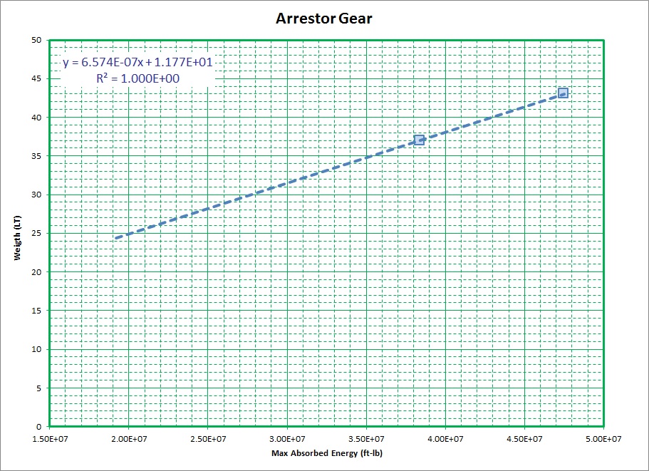
Although this data is limited to only two points right now, it
represents the best information that I have been able to currently
review and it can hopefully be used to develop weight estimates for the
other catapults listed in the
table above and/or to provide a designer with a means of estimating the
weights of other similar systems.
As with the catapults, it is also necessary to include a couple additional weigth items in order to get a better overall estimate of the total potential weight impact that the installation of such systems may have on a ship. Here I have used some basice rules of thumb for some of these weights as folows;
SWBS 185 - Structural Foundations - 8.84% of SWBS 586
SWBS 599 - Spares and Special Tools - 0.15% or so of SWBS 586
In addition, looking at Ref CVX for the US Mk7 mod3 Arrestor Gear it appears that each arrestor engine includes about an additional 1.6% its weight in hydraulic fluids (125 gallons of hydraulic oil @ about 7.2lb/gal).
Using the above data I have revised the table above as shown below to allow a user to investigate alternate arrestor gear installations.
| Arrestor Gear | Energy | Base Wt | w100+ | w500+ | Pullout Length (ft) | LZ width | |
|---|---|---|---|---|---|---|---|
| (ft-lb) | (LT) | (LT) | (LT) | Barricade | Wire | (ft) | |
| US Mk7 Mod2 | 38,373,000 | 37.0 | 3.3 | 37.7 | 388 | 349 | 120 |
| US Mk7 Mod3/4 | 47,500,000 | 43.0 | 3.9 | 43.7 | 409.5 | 349 | 120 |
| US Mk14 |
|
|
|
|
394 | 300 | 120 |
| UK Mk13 | 19,600,000 | 24.7 | 2.2 | 25.1 | 150 | 220 | 100 |
| UK DA2 | 30,000,000 | 31.5 | 2.8 | 32.0 | 181 | 265 | 100 |
Est Based off Estimated Max Energy
Est Based off Similar System
In addition typical wire spacing for the arrestor gear appears to be 40ft on US ships or 26ft on UK (1950 & 60 era) designs.
Est Based off Similar System
In addition typical wire spacing for the arrestor gear appears to be 40ft on US ships or 26ft on UK (1950 & 60 era) designs.
This document maintained by PFJN@mnvdet.com.