General Flight Deck Geometry Definition
Upone completion of the Landing Zone Layout the user then has the opportunity to define the overall flight deck geometry. The Image below shows the initial basic flight deck geometry that the user will (partially) define on the Base FDk Layout Tab of the spreadsheet. Here the colored points A through G are points where the user will provide some input on, either defining the longitudinal and/or transverse location of these points. The White, Gray and Black points H through P are points that get calculated by the spreadsheet based on the user inputs here and on the LZ Layout Tab.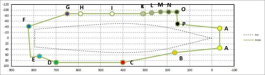
Below is a summary of the specifc inputs required by the user on the Base FDk Layout Tab
Hull Flare Angle in degrees
% Loa/LPP the the Flight Deck extends past the Waterline
Pt A - Forward Dk 1/2 Width (Y offset only)
Pt B - Forward Extent of Starboard Sponson (X offset only)
Pt C - Fwd Stbd Sponson Offset (X & Y location)
Pt D - Aft Stbd Sponson Offset (X & Y location)
Pt E - Aft Knuckle Pt (X location only, the spreadsheet will calculate the Y location based on the Landing Zone Geometry)
Pt F - Aft Port Stern Offset from Safe Pkg Line (Y location only, the spreadsheet will calculate the X location based on the Landing Zone Geometry)
Pt G - Aft Port Sponson Offset (X & Y location)
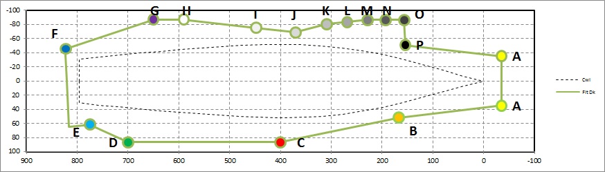
Pts H through P are dependent on the Landing Zone geometry and Landing Zone angle in relation to the ship's centerline. With repect to the angle between the Landing Zone and the ship's centerlin;
- if that angle is great enough that Pt O extends further to Port than the user input value for Pt G, then the flight deck will appear similar to the 1st flight deck image shown near the top of this page.
- if that angle is such that the distance from the ship's centerline to Pt O is less than the distance from the ship's centerline to Pt G then the ship's flight deck layout may look more similar to the 1st image below.
- if the angle is near 0 or even to starboard then the ship's flight deck layout may look more similar to the 2nd image below.
With respect to the calculated points, it should be noted that Pt P represents the point where the forward end of the landing zone would intersect with the "mirror image" of the line from A to B, and as such it more or less represents the forward most extent of sponsons on the Starboard side. Based on some rules of thumb on flight deck layout a minimum value for the location of the forward most extent of such a deck supporting sponson is sometimes given as 21 to 25% of LPP aft of the ship's forward perpendicular (FP). As such, if the location of Pt P is less than this distance aft of the FP a warning message is provided.
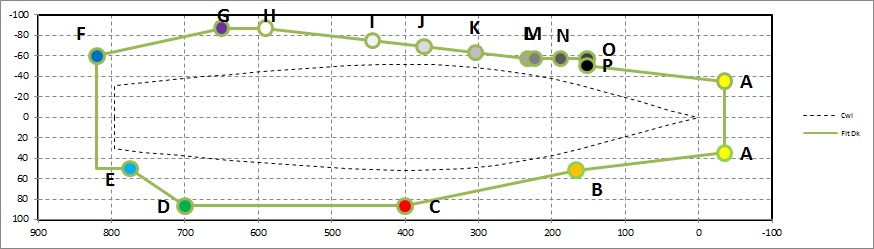
The figure below shows the resultant flight deck layout with the Landing Zone, and its associated Safe Parking Lines, etc is shown below.
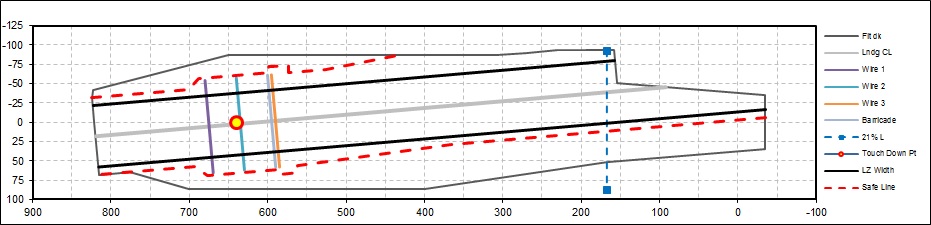
Note here that the dashed blue
line represents a distance 21% Lpp aft of the ship's Forward
Perpendicular (FP) which is given as a potential minimum desired
distance for major sponsons to extend outboard from the hull. For
the specific design shown above the required length of the landing zone
has lead to the forward end of the Landing Zone extending forward of
this location, and as such in the spreadsheet a warning message will be
given.
This document maintained by PFJN@mnvdet.com.