
Aircraft Carrier w200 (Main Machinery) Weight Estimating
For estimating a
design's SWBS Group 200 Main Machinery weight I have taken the weight
data provided in Ref CV1 and plotted it as shown below.
Unfortunately since the data that I have is based on existing vessels and previous design studies it is limited to only the machinery plant types and power output ranges of those vessels and designs. As such, using this datait is only possible to estimate the weights of steam vessels or lower powered (less than about 100,000 HP) gas turbine plants. However, since the data on catapults that I have is primarily for steam systems this allows for the design of steam CATOBAR vessels and either steam or small to mid-size gas turbine propelled STOVL or STOBAR designs.
Additionally I am also looking into trying to develop a means for estimating the weight of either an auxiliary boiler system or enlarged electrical plant to allow for designs which combine steam catapults with non-steam propulsion plants or electro-magnetic catapults on non-electric drive vessels.
In addition I have also added some data from two MIT Thesss entitled
"A Design Guide for Naval Ship Propulsion Plants" and a "Ship Synthesis
Model for Naval Surface Ships" as described on the webpage that I've
put together for w200 weights for Surface Combatants.
Currently I have focused primarily on Fossil Fuel and Nuclear Powered
Steam vessels but hope to eventually expand to additional gas turbine
and diesel options.
For the steam plants the individual weights of the major components of a ship's propulsion plant are estimated and summed together with an additional estimate of "other miscellaneous components" to give a total Main Propulsion Plant Weight. Because of the large size of propulsion plants likely for many large carriers, much of the weight estimating is done per "sub plant" where each "sub plant" is assumed to be near identical and there is assumed to be one "sub plant' per "shaft". Each "sub plant" is assumed to consist of a propulsor, shafting and support equipment, a reduction gear set, a steam turbine set, and a condensor and associated air ejectors. In addition to this, for these steam plants, the main machinery plant will also need to include either boilers or nuclear reactors to generate the steam that is used to drive the steam turbines. With regards to the boilers and/or reactors the user has two options;
The figure below shows the equations used for estimating the weight of these type propulsors, along with some data points for the fixed pitch proellers on similar ships.
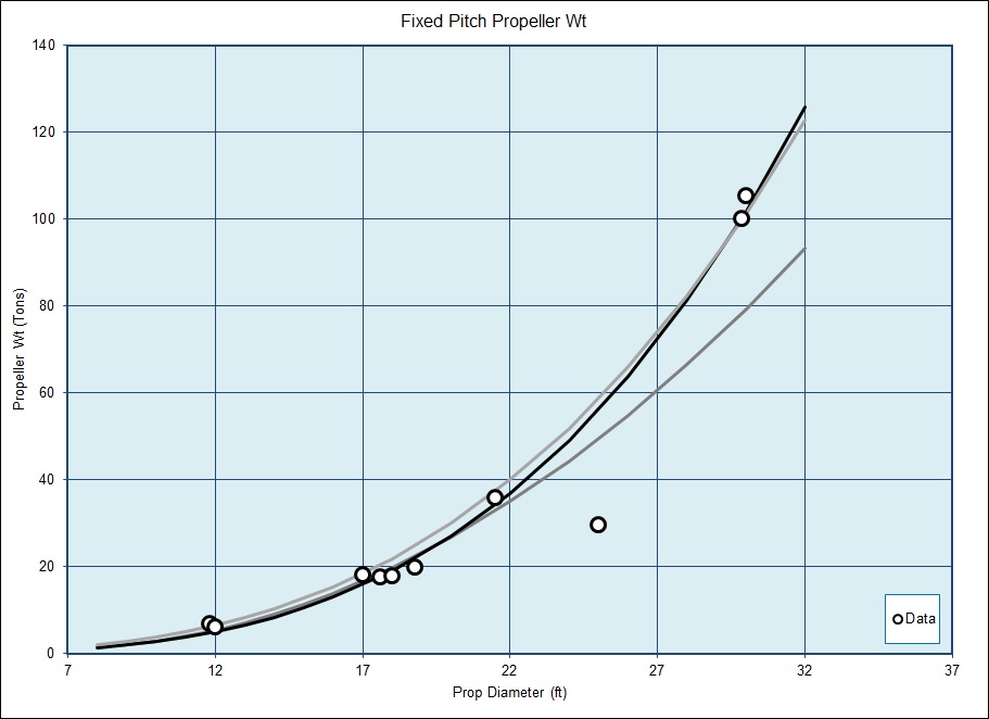
For a As shown in the above figure the Black and Lt Gray curves appear to show relatively good agreement with most of the data points, while the Medium Gray Curve appears to show more variance at larger propeller diameters. As such, the Black curve is used in the spreadsheet for estimating the weights of Fixed Pitch Propellers. The equation for the Black curve is;
Where M is a factor as defined in the Figure below.
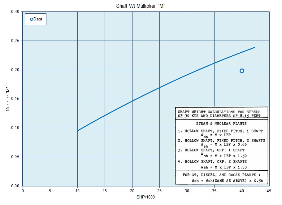
[ M = -0.00003 * ( SHP / 1000 ) ^ 2 + 0.006 * ( SHP / 1000 ) + 0.0383 ]
Reduction Gear
The steam turbines in each sub plant are assumed to be connected
to the shafting through a Locked Train Double Reduction (LTDR) gear set.
The method used in estimating the weights of these items is based on a
mix of the information in the reference theses and other sources.
the 1st step in estimating these weights involves determining the required reduction ratio of each stage and then determing the diameter of both the bull gear and pinions. Determination of these items requires;
Where the K factor is a measure of the gear and pinion's surface stress. Per Reference X, the K factor for Naval Gearing will vary from about 110 to 150, with a value of 110 recommended for the low speed pinion of a LTDR gear set and 140 recommended for the high speed pinion of the set.
From the reference theses the recommended 2nd & 1st Stage Reduction Ratios for a LTDR gear set is;
And
And finally, weight is assumed to be equal to roughly;
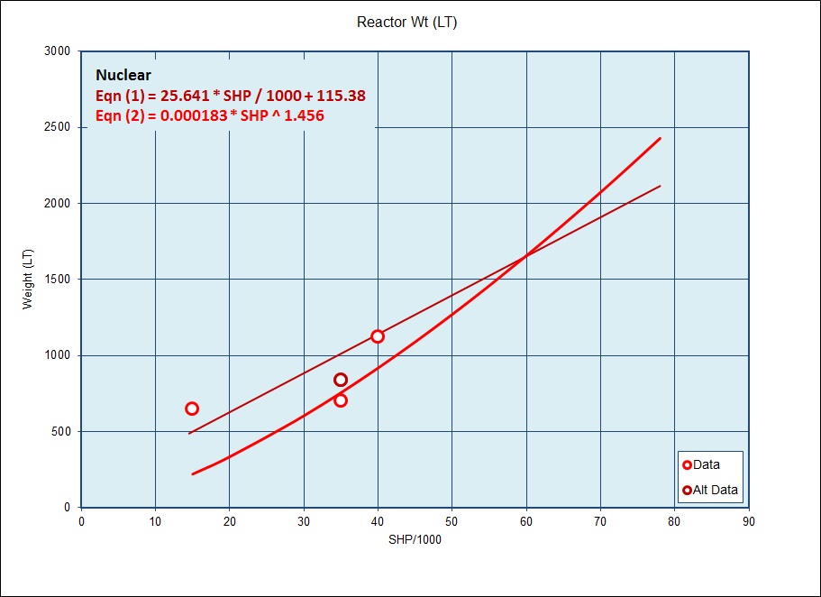
In the Reactor Figure the Red and Rust colored curves show the recommended weights for these items based on equations from the reference theses, while the Pink colored line shows a trendline through reference data points obtained from the website at this link -
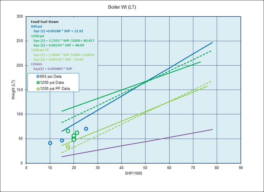
In the Boiler Figure the Blue Curve shows the recommended weights for 600 psi Boilers, while the Dark Green Curves show two different estimates for 1200 psi Boilers based on equations from the reference theses, and the Lt Green Curves show two different estimates for 1200 psi Boilers based on equations from the reference theses, and the circular data points show information for reference vessels. The Purple Curve is for COGAS type plants, which I haven't had a chance fully incorporate yet, but hope to soon.
While the limited number of data points for the boilers show reasonable agreement with the various equations from the reference theses, the data for the reactors doesn't show such good agreement, and as such I'm continuing to review those calcs and data.
For the steam plants the individual weights of the major components of a ship's propulsion plant are estimated and summed together with an additional estimate of "other miscellaneous components" to give a total Main Propulsion Plant Weight. Because of the large size of propulsion plants likely for many large carriers, much of the weight estimating is done per "sub plant" where each "sub plant" is assumed to be near identical and there is assumed to be one "sub plant' per "shaft". Each "sub plant" is assumed to consist of a propulsor, shafting and support equipment, a reduction gear set, a steam turbine set, and a condensor and associated air ejectors. In addition to this, for these steam plants, the main machinery plant will also need to include either boilers or nuclear reactors to generate the steam that is used to drive the steam turbines. With regards to the boilers and/or reactors the user has two options;
- steam for each "sub plant" will be provided by one or more boilers/reactors, or
- if the reactor or boiler is large enough, it can provide steam to more than one "sub plant"
Propulsors
For steam plants, fixed pitch propellers are assumed as the likely propulsor. From data in the reference theses the following relationships are suggested for suggested propeller diameter and rpm, though in the spreadsheet the user has the opportunity to enter alternate inputs as well;For Single Prop Ships: D = 2.60 * Draft ^ 0.629
For Multi Prop Ships: D = 4.28 * Draft ^ 0.428
RPM = 96.1 * Vsustained / Dprop + 52.15
For Multi Prop Ships: D = 4.28 * Draft ^ 0.428
RPM = 96.1 * Vsustained / Dprop + 52.15
The figure below shows the equations used for estimating the weight of these type propulsors, along with some data points for the fixed pitch proellers on similar ships.
For a As shown in the above figure the Black and Lt Gray curves appear to show relatively good agreement with most of the data points, while the Medium Gray Curve appears to show more variance at larger propeller diameters. As such, the Black curve is used in the spreadsheet for estimating the weights of Fixed Pitch Propellers. The equation for the Black curve is;
Weight FPP Prop = 0.143 * Dprop ^ 2 - 1.9 * Dprop + 7.53
Shafting & Bearings
Shafting weight for vessels with hollow shafts and fixed pitch propellers are based on the following equations;Single Shaft Vessels: Shaft Weight = M * Lpp
Multi-Shaft Vessels: Shaft Weight = M * Lpp * 0.66
Bearing Weight = 0.15 * ( Shaft Weight + Propeller Wt )
Multi-Shaft Vessels: Shaft Weight = M * Lpp * 0.66
Bearing Weight = 0.15 * ( Shaft Weight + Propeller Wt )
Where M is a factor as defined in the Figure below.
[ M = -0.00003 * ( SHP / 1000 ) ^ 2 + 0.006 * ( SHP / 1000 ) + 0.0383 ]
Reduction Gear
The steam turbines in each sub plant are assumed to be connected
to the shafting through a Locked Train Double Reduction (LTDR) gear set.
The method used in estimating the weights of these items is based on a
mix of the information in the reference theses and other sources.the 1st step in estimating these weights involves determining the required reduction ratio of each stage and then determing the diameter of both the bull gear and pinions. Determination of these items requires;
input rpm = the rotational speed of the steam turbines, with a value of 7800 rpm recommended as a default value
output rpm = the rpm of the propellers at design speed
High-Speed Pinion K factor
Low-Speed Pinion K factor
output rpm = the rpm of the propellers at design speed
High-Speed Pinion K factor
Low-Speed Pinion K factor
Where the K factor is a measure of the gear and pinion's surface stress. Per Reference X, the K factor for Naval Gearing will vary from about 110 to 150, with a value of 110 recommended for the low speed pinion of a LTDR gear set and 140 recommended for the high speed pinion of the set.
From the reference theses the recommended 2nd & 1st Stage Reduction Ratios for a LTDR gear set is;
R2 = sqrt ( Nin / Nprop ) + 3.0
R1 = Nin / ( Nprop * R2 )
R1 = Nin / ( Nprop * R2 )
And
dia ^3 = 126,050 * SHP * ( R + 1 ) / Np * 2.25 * R * K
As such;For the High-speed Pinion: d1^3 = 126,050 * SHP * ( R1 + 1 ) / Nin * 2.25 * R1 * K(1)
And for the 1st Reduction Gear: D1 = d1 * R1
For the 2nd (Low-Speed) Pinion and Gear;And for the 1st Reduction Gear: D1 = d1 * R1
d2^3 = 126,050 * SHP * ( R2 + 1 ) / ( Nin * R1) * 2.25 * R2 * K(1)
D2 = d2 * R2
D2 = d2 * R2
And finally, weight is assumed to be equal to roughly;
( 1 + f ) * reference volume of the gearset * 0.09
Where;f = is a factor to account for the structural weight and stiffness of the gear casing and a default value of 0.75 is assumed
the reference volume of each pinion or gear of the gearset = pi * d ^ 2 / 4 * 2.25
[Check this]
the reference volume of each pinion or gear of the gearset = pi * d ^ 2 / 4 * 2.25
[Check this]
Turbine Weight
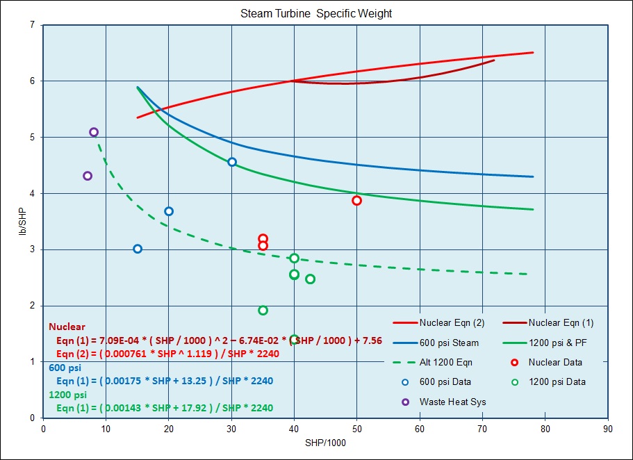
The figure below shows recommended Specific Weight for Steam Turbines (in terms of lb/SHP) for Nuclear Plants, 600 psi Plants, and 1200 psi Plants, as well as some data points for similar vessels. The Rust and Red Curves are for the Nuclear Plants and represent the different equations provided by the two different reference theses. The solid Blue and Green Curves represent the data for 600 psi and 1200 psi plants from one of the refeerence theses, respectively, while the dashed Green Curve is an alternate estimate for the 1200 psi units adjusted to better agree with data for similar vessels.Main Condensers & Air Ejectors
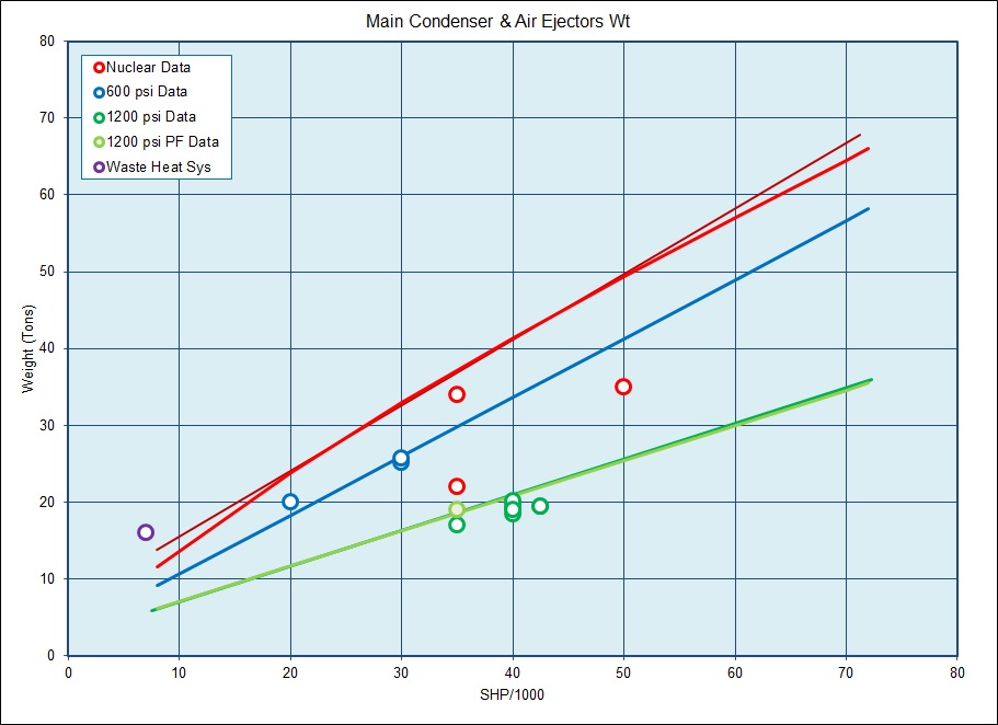
The figure below shows the estimated Main Condenser & Air Ejector weights for both Fossil Fule and Nuclear Powered steam plants. The Rust and Red Curves are for the Nuclear Plants and represent the different equations provided by the two different reference theses. The Blue Curve shows the data for 600 psi plants from one of the reference theses, while the Light Green and Dark Green Curves represent the data for 1200 psi plants, and the circles represent data for similar ships. In general, the trendline curves appear to show fairly good agreement with the data points.Reactors & Boilers
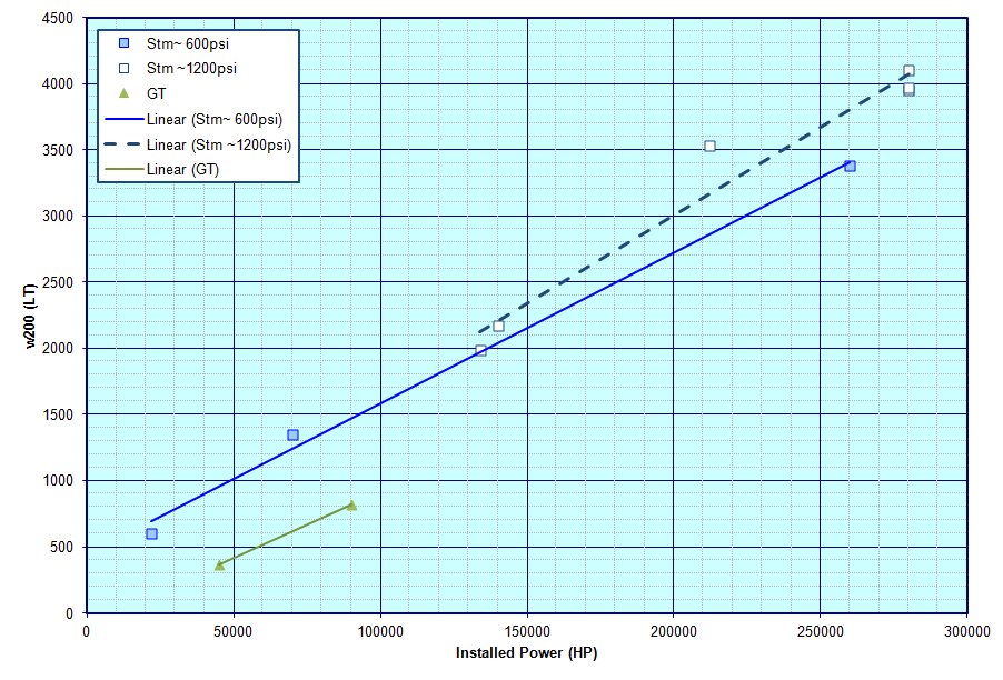
The figures below show trendlines and notional weight estimation equations for nuclear reactors and boilers from the reference theses and other data from the internet or ship data.In the Reactor Figure the Red and Rust colored curves show the recommended weights for these items based on equations from the reference theses, while the Pink colored line shows a trendline through reference data points obtained from the website at this link -
In the Boiler Figure the Blue Curve shows the recommended weights for 600 psi Boilers, while the Dark Green Curves show two different estimates for 1200 psi Boilers based on equations from the reference theses, and the Lt Green Curves show two different estimates for 1200 psi Boilers based on equations from the reference theses, and the circular data points show information for reference vessels. The Purple Curve is for COGAS type plants, which I haven't had a chance fully incorporate yet, but hope to soon.
While the limited number of data points for the boilers show reasonable agreement with the various equations from the reference theses, the data for the reactors doesn't show such good agreement, and as such I'm continuing to review those calcs and data.
Other Associated Plant Weights
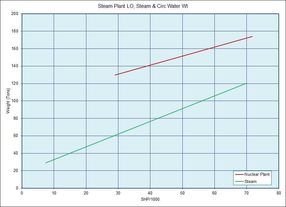
The figure below shows the weight estimate data for the other associated weights for both Nuclear and Fossil Fuel Steam powered vessels. This includes items such as the Lube Oil system, Circulating Water system, and Fuel Systems. The Rust colored curve is for Nuclear plants while the Green curve represents the data for Fossil Fuled steam plants.This document maintained by PFJN@mnvdet.com.