Aircraft Carrier w300 (Electrical Plant) Weight Estimating
For estimating a
design's SWBS Group 300 Electric Plant weight I have taken the weight
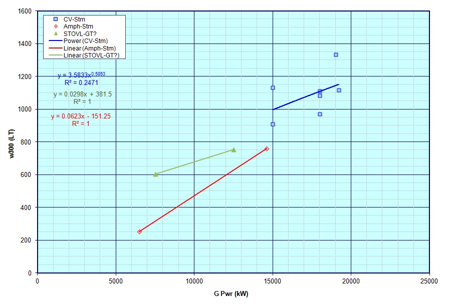
data provided in Ref CV1 and plotted it as shown below.
Unfortunately there appears to be a bit of scatter in the data no matter how I tried to plot it, and the best fit that I came up with was against installed propulsion plant power. As such I've gone ahead and tried to do a more detailed weight assessment for this group.

The figure below shows such a plot.

Unfortunately there appears to be a bit of scatter in the data no matter how I tried to plot it, and the best fit that I came up with was against installed propulsion plant power. As such I've gone ahead and tried to do a more detailed weight assessment for this group.

More Detailed Weight Assessment
Looking through the two reference theses used in the w200 Propulsion Plant weight estimates, it appears that for surface combatant vessels the w300 weight could be broken into perhaps three subgroups as follows;- the weight of the specific generators installed and their supporting equipment, which should likely be a function of the number, type and size of the specific generators installed
- the weight of the electrical switchboard, support equipment and spare parts, etc, which may likely be a function of the overall electric generating capacity onboard the ship, and
- the weight of the electical distribution and lighting systems onboard, which may likely be a function of the overall size of the vessel.
Estimate of Installed Electrical Generating Capacity
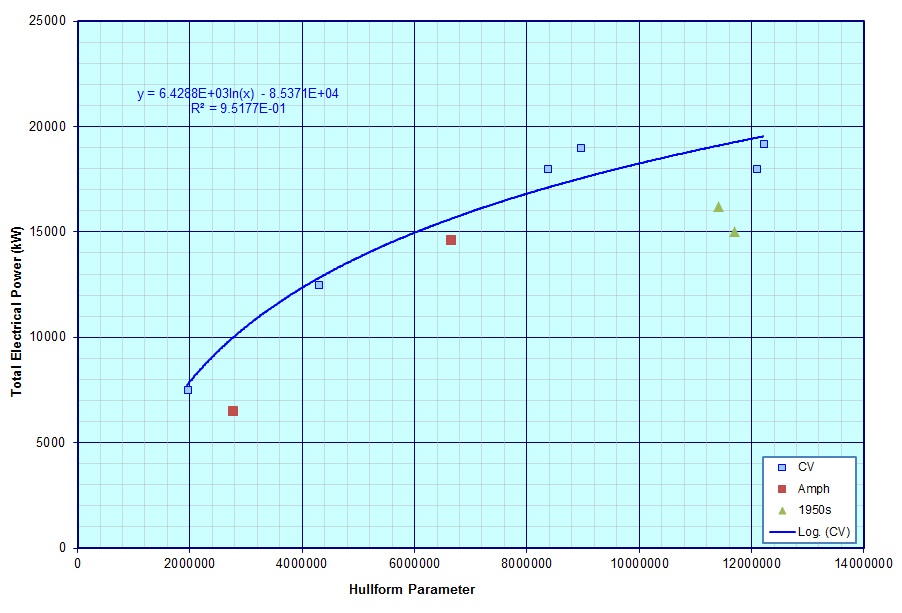
Typically in a ship design, the required installed generating capacity could be estimated by making an assessment of how much power various systems and components will require and under what conditions they will be in use (including maybe making some weighted averages, etc). However, for the current spreadsheet, I'm not sure that I have enough information to try that approach so, instead I have tried looking at how much generating capacity existing vessels and designs incorporated and trying to draw some trendlines from that data.The figure below shows such a plot.

Overall, the curve looks fairly
reasonable, but it only covers conventionally powered vessels and not
nuclear powered ones. From data in Dr. Freidman's book on "US
Carrier" and other stuff on the internet it appears that the total
installed electrical power on these type vessels may range from
44,000kW on CVN 65 to 72,000kW on CVN 68, with the new USS Ford Class
CVN 78, which uses electro-magnetic catapults, which is said to have
almost three times that amount of capability ( http://en.wikipedia.org/wiki/Gerald_R._Ford-class_aircraft_carrier ). Right now I do not have a trendline for recommendations for Nuclear type vessels.


Estimate of Generator Weight
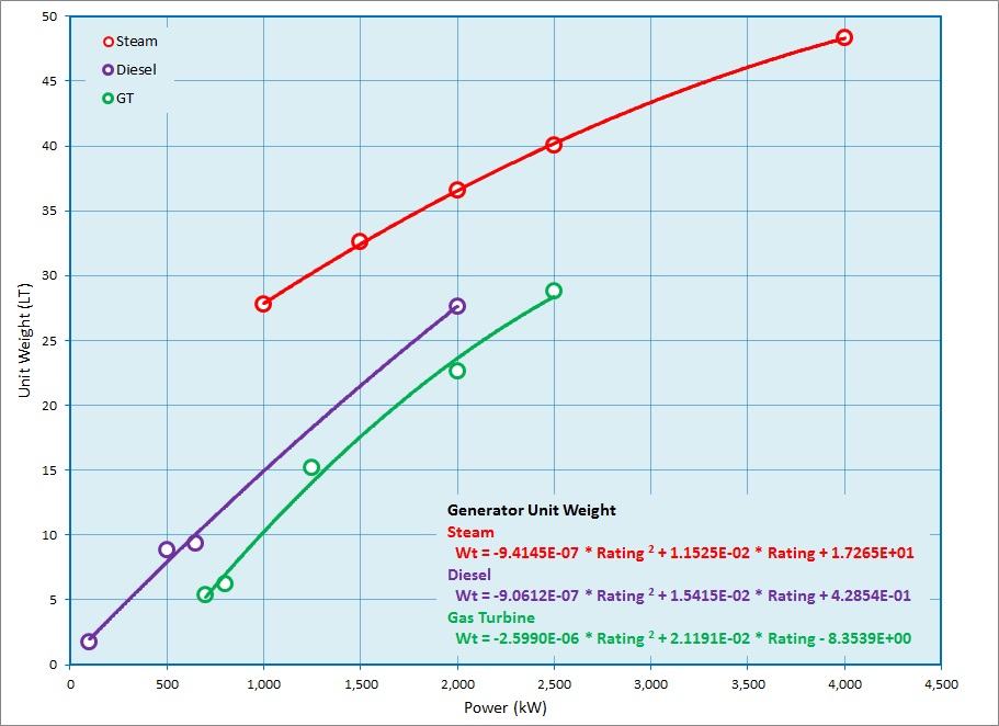
Below is a plot of weight of typical 60Hz electrical generators. The Red curve represents Steam Generators, while the Purple curve represents Diesel units, and the Green curve represents Gas Turbine units. Using this graph it should be possible to estimate the weight of the specific generators in a design.
Estimate of Electrical Switchboard, Support Equipment & Spares Weights
In one of the reference theses a weight breakdown was provided for the weights of the electrical switchboards, support equipment and spares, for surface combatabt vessels. Summing these estimates gives the following equation, which seems a reasonable for use in the spreadsheet for now.Wt = 0.003348 * Tot Inst Pwr + 4.57
Estimate of Electrical Distribution and Lighting Weights
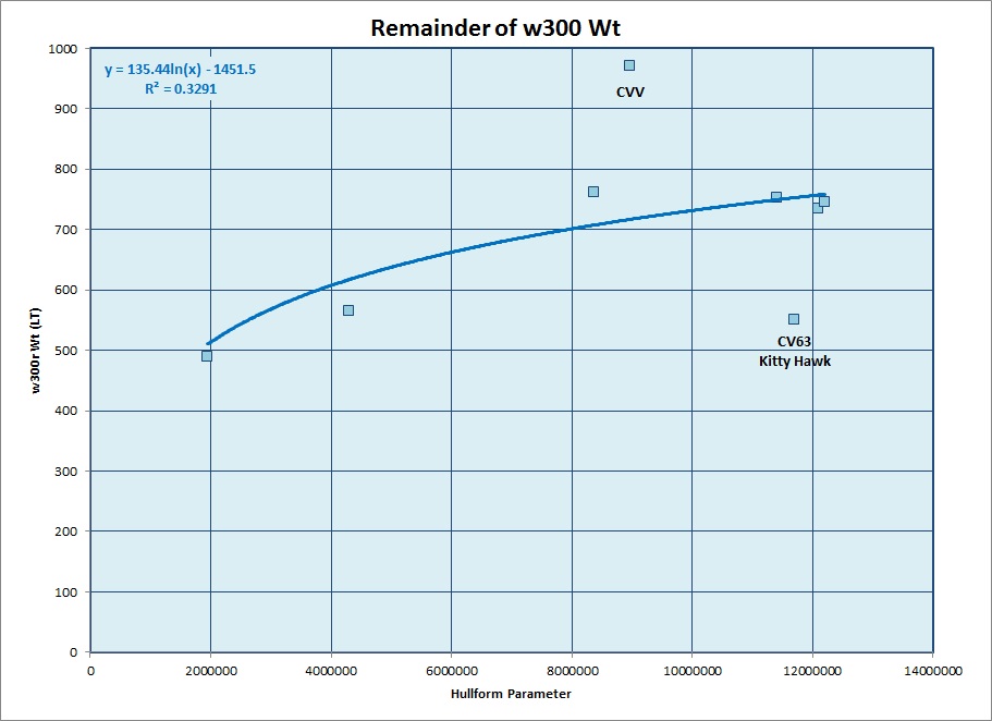
Using the above information I have subtracted off the estimated generator weights and switchboard, support equipment and spares weights to obtain a w300 remainder weight, which I belive should be composed primarily of the electrical distribution and lighting weights. I then plotted these values below to try and develop a trendline for estimating this weight for other designs, as shown below.
Unfortunately there are there
appears to be two outliers in this data. One is for a mid 1970s
design study, and the other is for CV63 the USS Kitty Hawk. I am
attempting to look further to see if I can determine why these two
vessels appear far off the trendline for the other vessels, but for now
I believe that this curve represents the best information that I can
locate at this time.
This document maintained by PFJN@mnvdet.com.