

Post-Processor Volume
Once a rough hullform is developed and its enclosed volume calculated, a useful next step can be to estimate the notional required total volume for the ship, based on information for similar vessels, and then to layout a rough approximation of the ship's superstructure.
Approximation of Volume Requirements
In the spreadsheet that I've set up the user imports the hullform data from the Hullform Post-Processor spreadsheet, as well as additional information on the ship's combat system and tankage requirements from the pre-processor and main iteration spreadsheets. Next the user will define a percentage for margins, with a suggested default value of about 5%.
Group 1 - Military Mission Volume Requirements
The 1st major segment of the ship's volume requirements is its Military Mission Requirements (Group 1). Although much of this is provided from data in the Pre-Processor, it is necessary to make estimates of a couple segments, such as the ship's C2 and Interior/Exterior Communications, as well as the ship's Weapons Support requirements and Flag facilities (if present).
An estimate of the ship's C2 and Internal/External Communications volume requirements can be approximated from data provided in Ref XXX as shown below;
C2+Int/Ext Comms Vol = 0.000018157*Disp^2 - 0.03155*Disp + 446.34

Weapon Support Volume requirements can also be estimated (also based on information from Ref XXXX) as;
Weapons Support Vol = 0.3577*sum( Other Weapon Systems Volumes )^0.8958
If the ship is intended to have Flag Officer Faciliities, the volume for these can also be added here, or estimated as;
Flag Officer Facilities Vol = (572.36*Nflag^0.8906)/3.2808^3
Where
Nflag = the number of personnel carried as part of the Flag Detachment
Summing these values with the volume requirements from the Pre-Processor for
- Radars
- Sonars
- ECM Equipment
- Guns
- Missiles
- ASW Weapons
- Mines
- Small Arms & Pyrotechnics
- Countermeasures
- Aviation Facilities
- C2+Int/Ext Comms
- Weapons Support
- Flag Officer Facilities
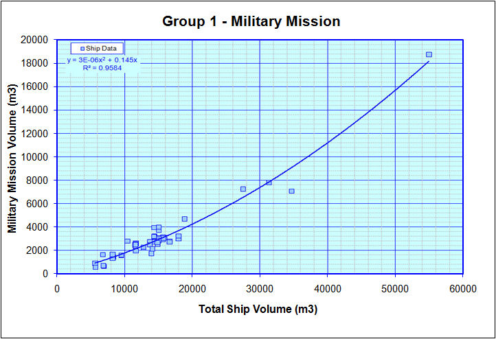
provides an estimate for the ship's Total Military Mission Volume. The spreadsheet will then display how the total Military Mission Volume of the design compares against a trendline of Military Mission Volume vs Total Ship Volume, as shown below.
Group 2 - Personnel Volume Requirements
Next it is necessary to estimate the ship's total personnel volume requirements. Based on data from similar ships, as well as data from a SNAME Presentation on ship design, a plot of notional Volume per Person is shown below.
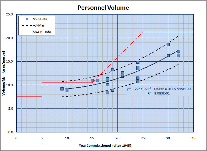
Here the data is plotted versus time (in terms of years after 1945) to help show how these requirements have increased over time. Specifically, the SNAME presentation suggested values of;
- 7.5 cu meters/person for ships in the 1940s
- 10.5 cu meters/person for ships in the 1950s
- 21.2 cu meters/person for ships in the 1970s
For the data from similar vessels the trendline plot provides the following info;
Vol/Person = 1.274E-02*(Year-1945)2 - 1.635E-01*(Year-1945) + 9.545E+00
Additionally, a range band of +/- 17.5% is also shown on this curve.Group 3a - Machinery Systems Requirements
Next an estimate of the notionally required Machinery Plant volume is made. Here I am currently using relationship curves from Ref XXX, but in the future I hope to add checks against other similar ships and other estimation sources.
Based on Ref XXX, Machinery Box Volume is estimated as;
- = (30851+1.472*SHP+7.735*KWInst)/3.2808^3 for Conventional Steam Ships
- = (0.2685*(SHP+KWInst/(0.8*0.746))^1.225)/3.2808^3 for Nuclear Powered Ships
- = (0.8346*(SHP+/kwinst/(0.8*0.746))^1.084)/3.2808^3 for Gas Turbine Ships
- = (893.21*SHP^0.4955)/3.2808^3 for Diesel Powered Ships
For Uptakes;
- = (-0.0005*(SHP/1000)^2 + 0.2123*(SHP/1000) - 0.139)/3.2808^3 for Conventional Steam Ships
- = 2000/3.2808^3 for Nuclear Powered Ships
- = (0.0023*(SHP/1000)^2 + 0.3556*(SHP/1000) - 1.3496)/3.2808^3 for Gas Turbine Ships
- = (-0.0018*(SHP/1000)^2 + 0.2862*(SHP/1000) + 1.0942)/3.2808^3 for Diesel Powered Ships
For additional space for shafts, bearings & props;
- = 0 for Single Shaft Conventional Steam or Nuclear Vessels
- = (15.90*LBP-3688.67)/3.2808^3 for Single Shaft Gas Turbine, Diesel, or COGAS plants
- = (0.0000210*LBP^3.034)/3.2808^3 for any Twin Shaft Vessel
Group 3b - Other Ship Operations Requirements
Requirements for Other Ship Operations are estimated as follows;
Controls
- Ship Control Volume = (0.00749*Lbp^2.258)/3.2808^3
- Damage Control Volume = (0.417*FLDisp+1062.74)/3.2808^3
- Offices Volume = (0.8889*FLDisp+541.68)/3.2808^3
- Maneuvering Spaces = (0.0183*(FLDisp*Vsus) + 2248.70)/3.2808^3
- Ventiliation Spaces = (2.092*FLDisp - 1516.62)/3.2808^3
Deck Auxiliaries
- Anchor Handling, Mooring, & Towing = (0.6413*LBP^1.432)/3.2808^3
Additionally the user will have to make a separate estimate of the volume set aside for Replenishment at Sea Equipment. Unfortunately I do not have any information to assist in estimating this yet, but I hope to add something here soon.
Maintenance
- Mechanical = (0.8036*FLDisp - 200.37)/3.2808^3
- Electrical = (0.1943*FLDisp+331.42)/3.2808^3
- Misc = (0.0291*FLDisp^1.284)/3.2808^3
Infromation in Ref XXX suggests that for Similar Ships;
- Ship Control Volume data may range between 66% and 103% of the above equation
- Offices Volume data may range between 77% and 269% of the above equation
- Ventiliation Spaces data may range between 75% and 165% of the above equation
- Mechanical Maintenance Spaces data may range between 85% and 133% of the above equation
- Electrical Maintenance Spaces data may range between 98% and 173% of the above equation
- Misc Maintenance Spaces data may range between 62% and 119% of the above equation
Group 3c- Tankage Requirements
Ref XXX provides the following equations for esimating tankage requirements;
- Fuel Oil Tankage = (105.85*w(816)^0.8532)/3.2808^3
- Reserve Feed Water Tankage = (0.5324*w(813)^1.9287)/3.2808^3
- Lube Oil Tankage = (39.0*w(814))/3.2808^3
- Diesel Oil Tankage = (27.93*w(817)^1.0798)/3.2808^3
- Misc Tankage = (40.0*w(820))/3.2808^3
- Stores & Supplies = (0.5353*(Complement*Endurance)+4422.87)/3.2808^3
- Ballast Tankage = (40.0*W(822))/3.2808^3
- Peak Tanks = (0.450*FLDisp-145.90)/3.2808^3
- Voids = (0.0000238*FLDisp^2.314)/3.2808^3
Addditionally, any tankage for small boats and cross flodding ducts etc would also have to be added by the user.
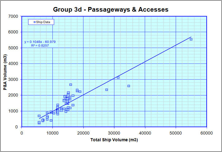
Group 3d - Passageways & Accesses
Based on data for similar ships the required volume for Passageways and Access can be estimated as;
P&A Volume = 0.1048 * Total Ship Volume - 60.979
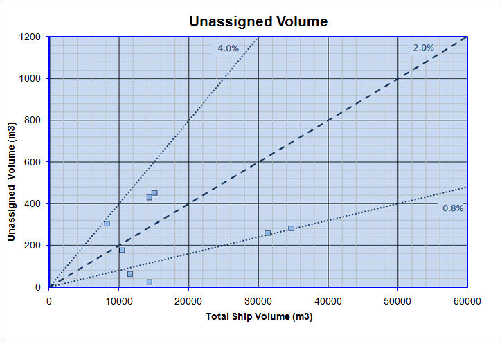
Unassigned Spaces
Based on limited data for Similar Ships, as shown below, it appears that a value between 0.8 to 4% would be reasonable for Unassigned Spaces, with a value of about 2% being close to average.
Superstructure Layout
Once an estimate of notional required total volume is made, it is then possible to lay out a notional superstructure for the ship. In the spreadsheet that I set up, this is done using a series of small, user defined, blocks, as shown below.
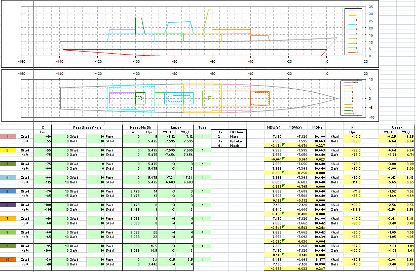
Here, the user first defines the fore and aft locations of one of the blocks. The spreadsheet eill then calculate the height of the wetherdeck and location of the deck edge at those locations, for reference. The user can set the base of the blocks at these heights to ensure that the block rests on the deck, or the user may input another value for superstructure blocks that rest at a higher level.
If the user wants to make a superstructure block extend to the deck edge, they can enter the calculated value for width. Otherwise they can enter any other value for narrower sections. For the example above, the Pink and Yellow blocks are full width blocks, while the Orange block forawrd of them is not.
Additionally the user has the ability to set a fore, aft, port, and starboard side slope for each block.
By stacking these blocks it is possible to make a fairly complex approximation of a ship's superstructure.
Also, the user has the option of defining if a given block is meant as a;
- Deckhouse
- Mast
- Uptake
- Mack (Combined Mast & Stack)
Eventually, I hope to add additionaly info to better define required exhaust volume requirements so that the user can check that the size of the blocks allocated to these uses is adequate or not.
Final Superstructure Check
Once all the above is done it is then possible to identify whether the superstructure layed out is within reasonable limits for the vessel, based off trend data from other ships, and other recommendations. In the plot below, it can be seen that from similar vessels the mena trendline for superstructure size is about 29% of a ship's hull volume, but that it can range from 10.5 to 52.5%
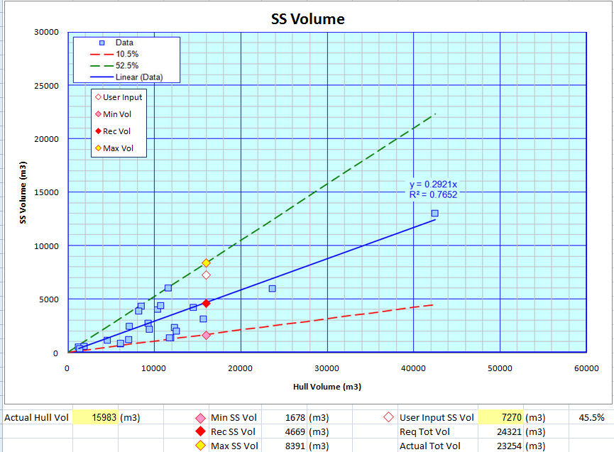
For the example shown above it can be seen that the superstructure layed out for this vessel is 45.5% of the ship's hull volume which is close to the upper limit, but still within the 10.5 to 52.5% range.