

Terminology
In this section I'll try and define some of the main terms that you may come across in discussion of a ship design.General
Load Waterline - The waterline at which a vessel floats at in its Full Load condition (as defined below under Weight Categories). It is measured from the point where the water surface intersects the bow to where the water surface intersects aft most point of the stern or transom.Design Waterline - The waterline at which a vessel floats at in its design condition. Typically a design condition is stated as either Full Load, Half Load, or some other typical operating condition. Right now for design purposes I have assumed all calculations (such as powering estimates and fuel consumption) are to be based on a ship's Full Load Displacement, and as such a vessel's Design Waterline and Load Waterline are currently assumed to be the same. As I understand it, however, in some navies things like powering and fuel consumption may instead be determined at a half load or part load condition. As such, eventually I may revise the calculations to allow designing ships for other loading conditions.
Dimensions
Length -
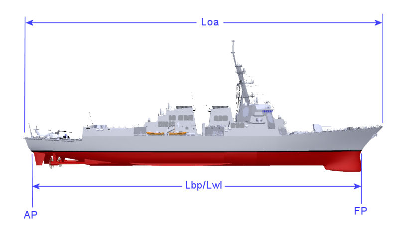
Length Overall (Loa) - In general on a ship the distance from the forward most point of a ship to its aft most point is called Length Overall .
Length on Design Waterline (Lwl) - In general this is the distance from the point where the bow of the ship crosses the Design Waterline to where the stern or transom crosses that waterline.
Length Between Perpendiculars (Lbp) - One issue that occurs in ship design, is that although you try and make your best estimates of weights early on, as the design and construction progresses, the overall displacement of the ship may begin to very from the design estimates as the actual weights of the individual components become better known. Typically margins are included in the weight estimate to allow for this, but sometimes there are late design modifications or unforseen events that may exceed these margins. As such, when finally delivered a ship's full load waterline may be different from its initial design estimate. To address this issue, it is typical to define a location at the bow of the ship (usually where it crosses the initial design waterline and define this as the Forward Perpendicular. Similarly (for naval vessels) it is typical to define a location at the stern or transom of the ship (usually where it crosses the initial design waterline and define this as the Aft Perpendicular. These two locations are then set as reference points on the vessel, and typically are not moved (even if the final full load displacement of the ship changes). [Side Note: On single screw merchant ships sometimes the aft perpendicular is instead defined as the rudder post (since this is an easily identifiable location on the vessel, but for our purposes we will use the transom location defined above as being more typical of naval vessel.] As such, for our purposes LBP and Lwl are considered to be the same.
Beam -
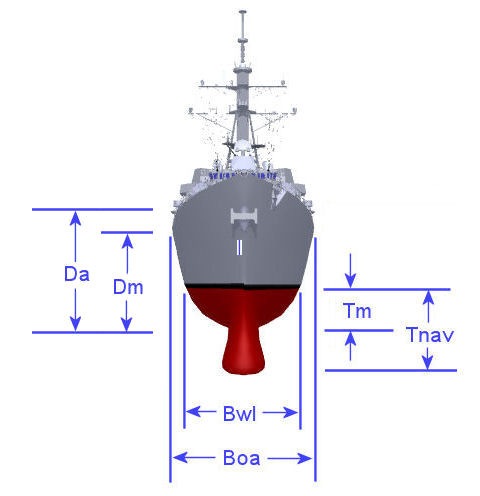
Beam Overall (Boa) - In general on a ship this is the distance across the widest part of the ship. On some modern vessels with significant flare, this can be appreciably greater than the width of the ship at its design waterline.
Beam on Waterline (Bwl) - In general on a ship this is measured as the maximum distance across the ship where it intersects the Design Waterline.
Depth -
Mean Depth (Dm) - In general on a ship this is the distance from the base of the keel to the main deck height amidships. Because some vessels have camber in the main deck (to help ensure that water will drain from the deck) the depth at centerline may be a little higher than the depth at side.
Average Depth (Da) - On some ships, such as those with extended focsle decks, the term Average Depth is used as an indication of what the equivalent depth of the hull would be if the focsle deck were extended along the full length of the ship, but reduced in height so that the total volume enclosed within it was the same as the shorter, full height space.
Draft -
Mean Draft (Tm) - In general on a ship this is the distance from the base of the keel to the height of the Lwl amidships. This measure of Draft does not include the impact of any appendages that extend below the bottom of the keel or the influences of vessel trim. It is basically a measure of the Draft of the bare hull of the vessel. It is important to note that the letter T is used to denote Draft while D is used to denote Depth. I believe that the letter T derives from German the word for Draft which is Tiefgang.
Navigational Draft (Tnav) - On some ships, appendages such as Sonar Domes and propellors can extend a fair distance below the ship's keel. Additionally, if the the loading of the ship were such that the ship was operating with trim, the bow or stern of the vessel could be lower in the water than the keel at midships. As such, Navigational Draft is a measure of the Draft of a vessel taking into consideration any appendages that extend below the keel of the ship and any impacts of vessel trim. It basically represents the depth of water at which the lowest point of the ship would touch bottom when the ship is at rest in calm water. Operationally, because of the impacts of wind, waves, and tides as well as certain shallow water flow effects that can cause a ship to sink lower in the water as the ship's speed increases, for navigational purposes you really need a certain additional margin of distance between a ship's navigational draft and the local water depth to operate safely in shallow waters.
Hullform Definition
Basic Coefficients - There are a number of coefficients and other parameters that can be calculated for a vessel to help give an simple defintion to its hull shape and form, or other characteristics. These coefficients and parameters are often used in early stage resistance and powering estimates, seakeeping estimates, and stability calcs. Some of these more common coefficients and parameters are defined below.Block Coefficient - A vessel's Block Coefficient or Cb is one of the most basic coefficients that is used to help define and categorize a vessel's hullform shape. A vessel's Block Coefficient is defined as the ratio of the volume contained within hull below the waterline as )shown in Red in the figure below) compared to the volume of a block whose length is equal to the vessel's Length between perpendiculars, and whose width is equal to the vessel's waterline beam, and whose height is equal to the vessel's mean hull draft (shown below as a Blue Box. Block Coefficient is a handy term for relating the relative fullness of a ship's underwater hullform and is sometimes used in equations for estimating resistance, seakeeping and stability, etc. Very full ships, like bulk carriers or large tankers can have block coefficients approaching 0.90 whereas faster vessels, including modern naval surface combatants can have Block Coefficients as low as 0.45, or so (as shown in a Figure on the Initial Hullform Definition page).
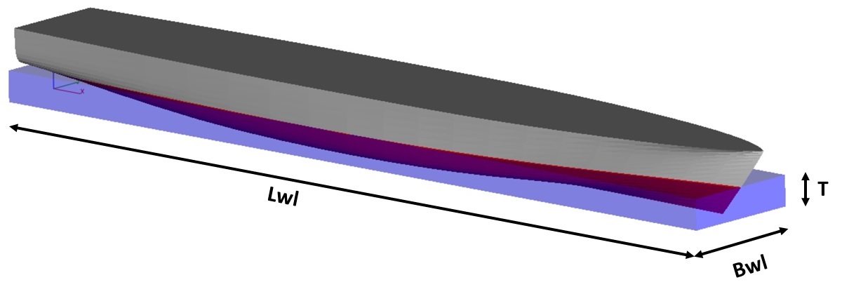
In accordnace with Archimedes Principle, if you assume a standard density for salt water of 35 cubic feet per Long Ton (or 1 cubic meter per 1.025 metric tonnes) then:
- Cb = Displacement * Density / (Lbp * Bwl * Tm)
However, when doing this calculation you need to make
sure that you are using Lbp, Bwl, and Tm, and not Loa, Boa, or Tnav
otherwise you can get incorrect results.
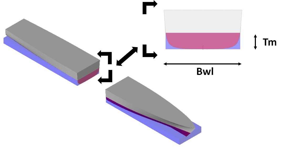
Midships Area Coefficient
- A vessel's Midships Area Coefficient or Cm is another basic coefficient, however
whereas a ship's Block Coefficient is a three
dimensional term (based on length, beam, and draft) a ship's Midships
Area Coefficient is two dimensional, being related only to
a vessel's beam and mean draft. In general if you were
to cut a ship in half at its mid-length, as shown in the figure below then its Midships Area
Coefficient would be equal to the ratio of the cross sectional
area of the hull below the waterline at that section (shown in the
Figure below in Red) divided by a
box whose width is equal to the vessel's waterline beam (Bwl) and whose
height is equal to the vessel's mean draft (Tm) (shown in the Figure below in Light Blue).
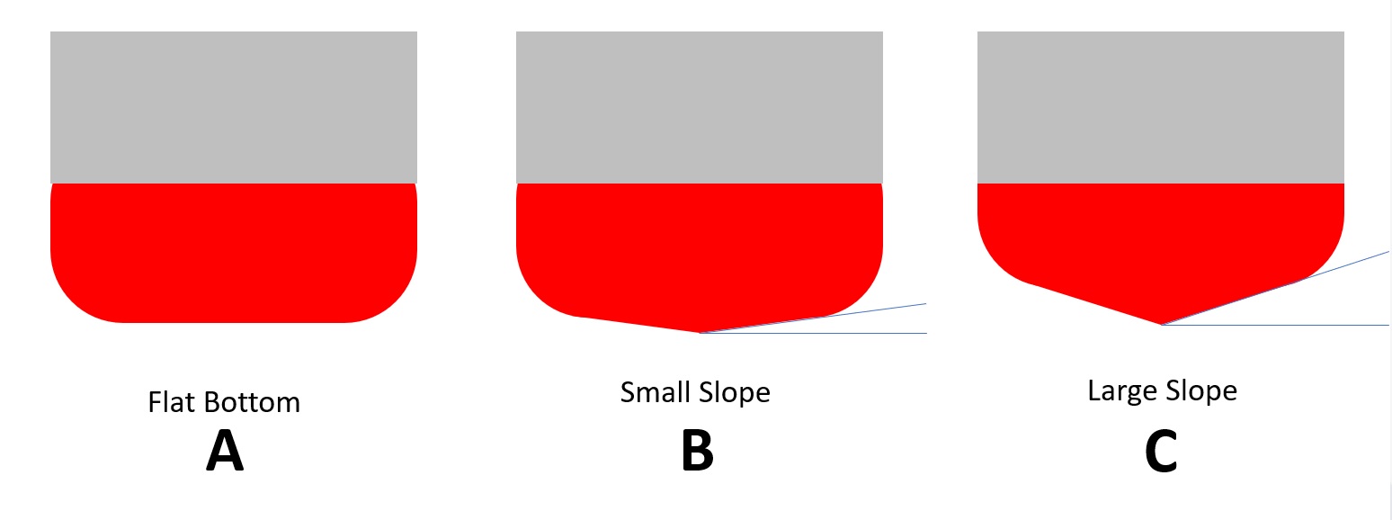
For vessel's with a high Block Coefficient, it is not uncommon for the
hull cross section at its midlength to have flat sides and a flat
bottom, with a simple radius at the turn of the bilge (as shown for
section (A) in the Figure below) [Add Figure].
Such a section shape is described as having "no deadrise".
Sometimes, however, even for ship's with a relatively full Block
Coefficient, the the hull bottom may have a small amount of slope to it
(as shown for section (B) in the Figure below). This type section
shape is typically described of as having "modest deadrise".
Finally, for ship's with relatvely low Block Coefficients
it is not uncommon for the hull bottom to have a greater slope to it
(as shown for section (C) in the Figure below) which is typically
described of as having a "high deadrise".
For conventional type vessels, mid-length is relatively close to the
vessel's section of maximum area, and sometimes the term Midships
Area Coefficient and Maximum Sectional Area Coefficient are
used sort of interchangeably, though in reality they can be a little
different from each other. For our purposes, a ship's Maximum
Sectional Area Coefficient is really of more importance
to us, as it is more handy for use in defining hull shape, etc.
As such that is what I intend to use in my calculations, though for
alot of the ships I have collected data on its not fully clear if what
they have reported is Midships Area Coefficient or Maximum
Sectional Area Coefficient and occassionally I know I will
inadvertantly refer to Midships Area Coefficient when I
really mean Maximim Sectional Area Coefficient. As
I noted above though, for the most part for conventional type vessels
the two terms should be relatively similar, and hopefully it won't
cause too much confusion.
Prismatic Coefficient
- A vessel's Prismatic Coefficient or Cp is coefficient related to both a ship's Block
Coefficient and its Maximum Sectional Coefficient.
If you were to take a ship's Maximum Sectional Coefficient
and stretch it along the length of the hull, as shown in Light Blue in the Figure below [Add Figure] you would have a prism whose
volume is equal to Lbp * Bwl * Tm * Cm.
The vessel'sPrismatic Coefficient is then equal to the ratio of the volume of the hull below the waterline (shown in the Figure below in Red) divided by the volume of this prism (as shown below in Light Blue). Mathematically, a vessel's Prismatic Coefficient is equal to its Block Coefficient divided by its Maximum Sectional Coefficient or in other words;
- Cp = Cb/Cm
Waterplane Area Coefficient -
Displacement Length Ratio -
Waterplane Inertia Coefficient -
Vertical Prismatic Coefficient -
Other Hullform Parameters
Half Entrance Angle -
Longitudinal Center of Buoyancy Location -
Wetted Surface Area -
Transom Area Coefficient -
Transom Beam Coefficient -
Transom Draft Coefficient -
Cubic Number -