Conventional Marine Steam Boilers
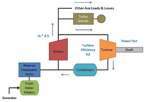
The notional rating of 28,750 HP per catapult (or 57,500 HP for a pair of catapults) for C13-2 type catapults appears to be similar in size to the main propulsion plant sizing for many frigate and destroyer sized vessels. As such, an initial thought might be to use the methodology and trendline relationships used for sizing such main propulsion plants to make an estimate of the overall size of such an auxiliary steam plant for supporting steam catapults on non-steam propelled vessels. However, on closer inspection a couple issues arise.Specifically, because an overall efficiency for a steam catapult system of 5.9 to 6 % was already included in determining the estimated 28,750 HP per catapult requirement noted above, this value more correctly represents the power output required at the boiler outlet while, for a notional propulsion plant the HP rating reflects the output power at the propeller shaft and not the power output of the boilers themselves. In a main propulsion system, there will be losses, additional loads and efficiency issues that would have to be addressed which would mean that the actual power output at the boiler(s) will likely be a fair bit higher than the power as measured at the propeller shafts, as shown in the figure below.
In looking at boiler data for several ships, including;
- the USS Massachusetts BB-59 (from the HNSA site)
- the
USS Farragut DLG-6/DDG-37 (from a report entitled "Integrated Shipboard
Main Propulsion Control System" by the Naval boiler and Turbine
Laboratory)
- a typical post WWII US Destroyer boiler (from the book Principles of Naval Engineering)
- the USS Fletcher (from the book "Naval Boilers" by (Robert Latham)
- a Pressurized 1200 psi boiler (from the "Naval Boilers" book)
- a typical 1956 era CV (from the "Naval Boilers" book)
- a WWII era destroyer escort (from the "Naval Boilers" book)
- another non-referenced boiler (from the same book)
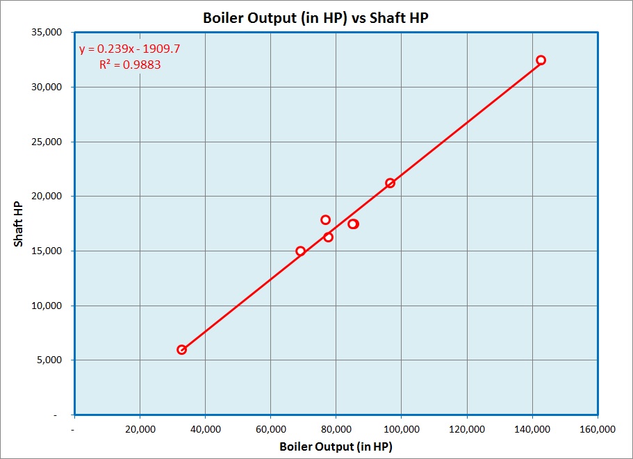
Based on the above trendline I've tried to adjust the equations for boiler weight, combustion air system weight, fuel oil system weight and uptakes weight to this "Boiler Output Power" to assist in estimating those weights.
As such, I have decided that rather than trying to use the trendlines that I have for main propulsion plants it might make more sense to try and estimate the weights of a conventional boilers on a trendline for auxiliary naval boilers where;
- aux boiler wt (in LT) = 0.0013 * Total Steam Flow Required (in lb/hr)
In trying to visualize the overall system though, a couple thoughts come to mind. As I understand it, reliability and availability considerations suggest that rather than a single catapult and boiler onboard a vessel, two or more units may be desirable. Additionally, the long time period required to bring a boiler online from a cold start would seem to suggest that at least one boiler should be on line during most operations, with perhaps an additional boiler(s) being available to be brought online to support large scale launch operations (such as a full airwing or near full airwing launch), and/or allowing all the boilers to be "cycled" over time so that maintenance and repairs can be conducted on the units not currently in use.
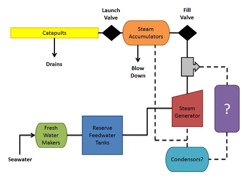
If it is necessary to maintain one boiler online at some level of output while a ship is underway in order to support potential intermittant catapult operations throughout the day, I would suspect that it would likely make sense to make it part of a "closed" system where steam that is being generated but not needed for use by the catapults at the time could be condensed and recaptured for use as feedwater, rather than requiring make up feedwater to be generated. As such, my thoughts would be that the auxiliary steam system in such a set up would likely be a "closed" (or mostly "closed") system with an "open" branch for the catapults as shown in the notional layout shown previously.
In such a system there would likely be at least two boilers, with one kept on line at most times and the other(s) being brought online in order to support a planned launch scale airwing launch, or to allow the 1st boiler to be brought offline for maintenance and repair. In addition I would suspect that the condensor(s) would have to be sized to accommodate regular typical operations as well as large scale air operations.
In additon to the above, I would also suspect that the reserve feedwater tankage would have to be sied to allow for enough reserve feedwater to support a large scale (full airwing or near full airwing launch) with freshwater makers sized to ensure that the tanks can be replenished quickly enough to support the total number of intended fixed wing aircraft sorties in a given time period.
Finally, if the main system is set up as a mostly "closed" system with any steam that is generated but not used by the catapults being re-condensed in the condensors and returned to the boilers as feedwater, the thought arises as to whether that steam could be put to use for other additional purposes rather than just dumping its thermal energy overboard via the condensors. The figure below shows the estimated weights of the condesors for such a system, based on the trendline data for main propulsion plants. Here a single condensor for a 28,750 HP 600 psi boiler would be about 25 LT.
My
preliminary assumption is that
for a two C13-2 catapult setup, the onboard auxiliary steam system will
likely consist of two catapults, two equally sized boilers, two
condensors and all the required support equipment for the two boiler
and two condesor system. From the image below the total the
support equipment weight would be about 101 LT based on the trendlines
for main propulsion plants. As such the total with of the steam
system would be 2 * 40.5 + 2 * 25 + 102.1
= 233 LT, which does not include the weight for the tankage or
freshwater
makers.
A couple potential thoughts come to mind, such as using this steam to either power the freshwater makers, support shipboard heating and/or potentially even driving steam turbogenerators (which would represent the "Purple" box with the large Question Mark in the concept figure shown below). Each concept would seem to offer some potential advantage and disadvantages.
For example, while using the excess steam to power freshwater makers would seem to make some sense since a large amount of makeup feedwater would be required in such a system (to support the steam lost in operating the catapults) a potential shortcoming of trying to make use of steam in such a manner would likely be that when the requirements for additional makeup feedwater is greatest (during high-intensity air operations) is also likely the time when that excess steam is likely to be least available. It may be possible that if sufficient feddwater tanakge is available though, producing this feedwater during periods of relatively low intensity air operations may be feasible.
Alternatiely, the use of excess steam as part of the ship's own heating system may be feasible if the ship is outfitted with a steam heat system and if the loss of steam for extended periods of time during periods of extended air operations is considered acceptable.
The third option mentioned above would potentially be to use any excess steam to drive turbogenerators to assist in developing electrical power onboard the ship. The potentail main drawback that would seem likely here is that I believe that such a system would not necessarily allow for fewer diesel or gas turbine generators to be fitted onboard the ship, as during periods of high intensity air operations where excess steam would likely not be available, diesel or gas turbine generators would be needed to make up the power that the steam turbogenerators would not be able to provide. As such, in such a setup any steam turbogenerators onboard the vessel configured to make use of any excess steam not directly needed for steam catapult operations would likely be used to allow the diesel and/or gas turbo-generators onboard the vessel to be taken offline and put on standby when the steam turbo-generators are in use to help reduce the operating hours of those systems. As such, in such a system, such steam turbogeneraotrs would be "supplemental" to the other existing systems and used primarily to make use of the energy in the steam that otherwise would be going to waste (as well as reducing the operational hours on the other electrical generating units).
Since I have not yet had a chance to
investigate fuel loads and such, I'm going to hold off on assuming any
specifc item in the "Purple" box of the notional layout sketch above.
This document maintained by PFJN@mnvdet.com.