
w200 - Propulsion Plant - Weight Estimating
As discussed in the Terminology section there are several types of power plant configurations suitable for modern naval vessels. Some of the most typical include:- Steam plants,
- Diesel plants,
- Combined Diesel Or Gas Turbine (CODOG) plants
- Combined Gas Turbine Or Gas Turbine (COGOG) plants, and
- Combined Gas Turbine And Gas Turbine (COGAG) plants
For Diesel Plants, for naval vessels this typically includes plants with one or more diesels geared together on each shaft. If more than one diesel is provided on each shaft the plant may sometimes be discribed as a Combined Diesel and Diesel (or CODAD) plant, as the ship may typically cruise using only one engine per shaft, but would clutch in the other engine(s) to attain full sprint speed. In general, looking at data for several typical surface combatants the propeller rpms appear to be in the range of about 150 to 300 rpm which is a bit lower than the shaft speed of most Medium Speed or Medium/High Speed Diesel engines. As such, directly connecting a diesel engine to the shaft for a naval surface combatant is not typically a viable option.
Combined Diesel Or Gas Turbine plants are propulsion plants where the vessel is fitted with diesel engines sized to allow the vessel to attain its cruise speed, but which also have gas turbines installed for operating at higher speeds. The way these plants are configured the diesel engines do not run when the vessel is operating at high speed due to the complexity of the gearing that would be required to allow the vessels to operate either with only the diesels at lower speeds, or with both the diesels and gas turbines together at higher speeds. In this type plant high-speed operations are done solely on the Gas Turbines. Hence these type plants are referred to as diesel "OR" gas turbine plants.
Recent advances in gear design and control system technology, however, have made it less difficult to design a plant where the diesels and gas turbines both can operate together at high speeds. (I belive that the German F124 and the US Coast Guard's National Security Cutter are both configured this way). Such a plant would be referred to as a Diesel And Gas Turbine plant.
Similar to the Diesel Or Gas Turbine plants, a Gas Turbine Or Gas Turbine plant is a plant where the vessel is fitted with small gas turbines sized to allow the vessel to attain its cruise speed, but which also have larger gas turbines installed for operating at higher speeds. The way these plants are configured the small gas turbines do not run when the vessel is operating at high speed. I believe that several classes of Royal Navy vessels from the 1970s (such as the Type 21, Type 22, and Type 42) all have such type plants.
For Gas Turbine And Gas Turbine plants, these are vessels where the main propulsion plant consists of two or more gas turbines geared together such that lower speed operations can be conducted on only one engine, but for higher speed operations the other gas turbines are also clutched in. I believe that the US Navy's FFG7, DD963, CG47/51, and DDG51 class vessels are configured this way.Here is a rough layout of how I intend to put this section of the evaluation tool together.
In addition to the above there are also some additional configurations such as;
- Combined Gas Turbine and Steam (COSAG) plants
- Combined Nuclear and Steam (CONAS) plants
- Combined Gas Turbine and Steam (COGAS) plants
- Combined Diesel Electric and Gas Turbine (CODLAG) plants
- and other various type of electric transmission plants
At this time this methodology covers Nuclear powered steam plants, Conventional and Pressure-Fired 1200 psi steam plants, Combined Diesel or Gas Turbine (CODOG) power plants, and Combined Gas Turbine or Gas Turbine (COGOG) power plants. I am currently also looking into additional information in order to extend these calcs to cover other plant configurations including Combined Steam and Gas Turbine (COSAG) plants, Combined Gas Turbine and Gas Turbine (COGAG) plants, Combined Diesel and Gas Turbine (CODAG) plants, and Geared or non-Geared Diesel Plants (including Low Speed Diesels connected directly to the shafts as well as Combined Diesel and Diesel (CODAD) plants).
The methodology outlined in Ref 200-1 breaks down the overall w200 weight into the following components:
- Energy Conversion and
Power Generartion Equipment
- Transmission Equipment
- The Propulsors
- Other Components such
as Controls, Auxiliaries, and Support Systems
Energy Conversion and Power Generation Systems
With respect to a diesel or gas turbine based plant, the diesel or gas turbine serves both as the energy conversionand power generation device, whereas for a steam type plant the oil fired boiler and/or nuclear reactor serves as the energy conversion device and the steam turbines serve as the power generation device. The transmission equipment include both the reduction gear (and clutches) as well as the propulsion shafting and shaft bearings. Currntly the propulsors include either fixed pitch or controllable pitch propellers.
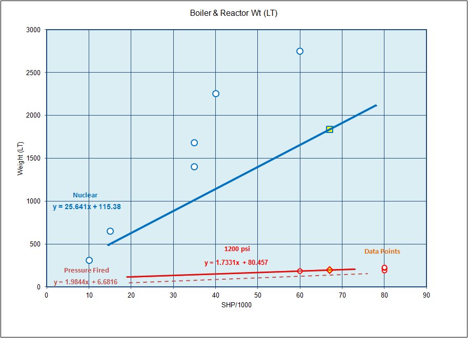
Below is a graph showing the nominal weight of both nuclear reactors and pressure-fired or conventional 1200 psi steam boilers, as taken from Ref 200-1 with added data points from the Federation of American Scientists Website (Ref 200-3) an internet article on Naval Reactors (Ref 200-4) and some data on other conventional ship plants.
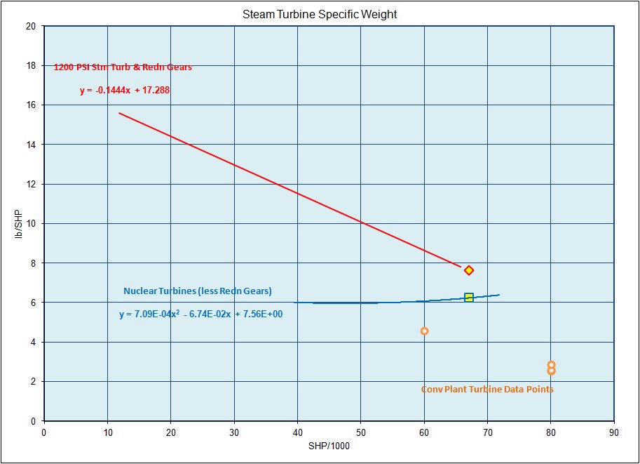
Next is aplot showing the specific weight (in terms of lb/HP) for typical steam turbines, with some additional data points for real ships and design studies added for reference. Please note that for the conventional 1200 psi steam turbines (and the Pressure-Fired steam plants turbines) the specific weight given includes both the turbine weight and the weight of the plant reduction gear. However, for the Nuclear Plants the specific weights listed is only for the turbines themselves and the weight of the reduction gears will have to be estimated separately.
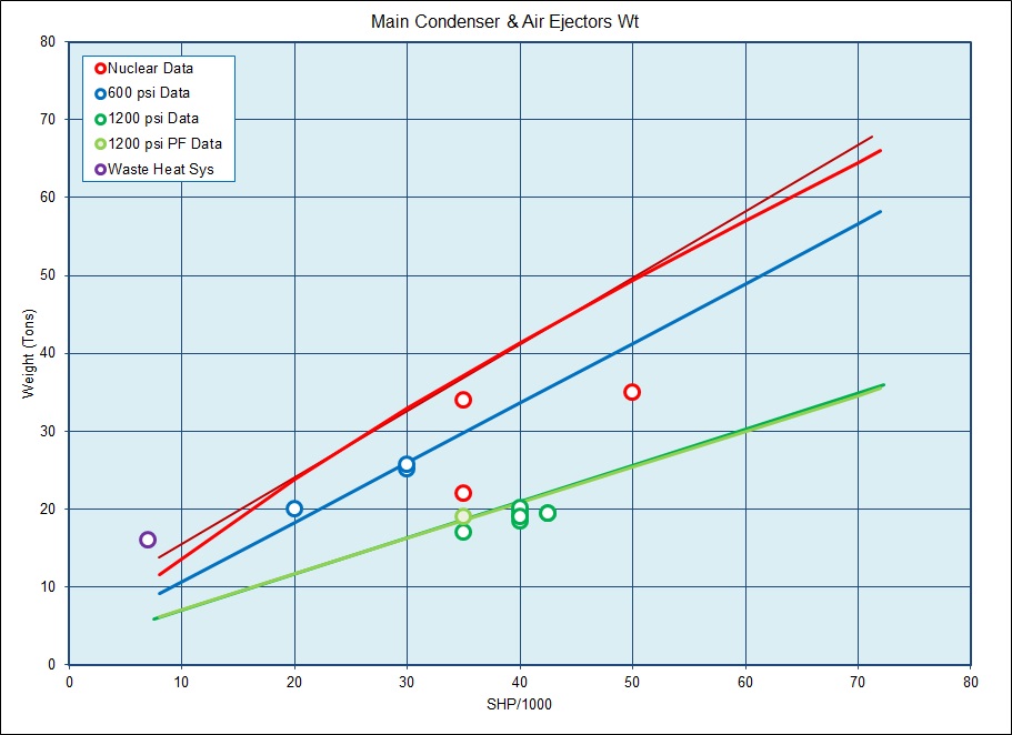
Next is a plot of the estimated weights for Main Condeser and Air Ejectors for the above steam plants.
For Gas Turbine plants here is a table of data for many current US &/or Western naval gas turbines.
| Type | Normal Rating |
Specific Weight |
Maximum Rating |
(lb) |
||
| (HP) |
(sfc)
[lb/HP*hr] |
(lb/HP) |
(HP) |
(sfc) [lb/HP*hr] | ||
| LM2500 | 20,000 | 0.569 | 11,375 | |||
| LM2500 | 20,000 | 0.41 | 0.580 | 27,000 | 0.39 | 11,600 |
| LM1500 | 12,500 | 0.58 | 0.600 | 14,000 | 0.57 | 7,500 |
| LM100 | 1,000 | 0.65 | 0.350 | 350 | ||
| TGP/GTPF 990 | 5,000 | 0.46 | 0.640 | 6,200 | 0.44 | 3,201 |
| FT4A-2 | 24,200 | 0.50 | 0.587 | 30,000 | 0.48 | 14,200 |
| FT4A-12 | 26,950 | 0.51 | 0.527 | 31,500 | 0.51 | 14,200 |
| FT4A-14 | 31,150 | 0.52 | 0.459 | 34,700 | 0.52 | 14,300 |
| FT4C-2 | 35,500 | 0.47 | 44,100 | 0.46 | ||
| FT12A-3 | 2,500 | 0.82 | 0.460 | 3,770 | 0.72 | 1,150 |
| FT12A-6 | 3,150 | 0.74 | 0.365 | 4,180 | 0.71 | 1,150 |
| 501K | 3,780 | 0.54 | 0.661 | 2,500 | ||
| T3001 | 3,000 | 0.56 | 1.833 | 3,120 | 0.55 | 5,500 |
| TF12A | 1,000 | 0.72 | 0.920 | 1,100 | 0.62 | 920 |
| TF14B | 1,250 | 0.60 | 0.736 | 1,475 | 0.59 | 920 |
| TF25A | 2,000 | 0.63 | 0.510 | 2,200 | 0.62 | 1,020 |
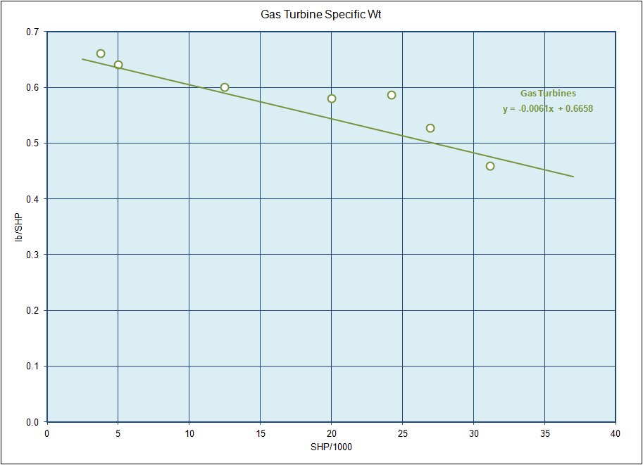
In addition here is a plot of gas turbine specific weight that can be used to help estimate the weight of other gas turbines.
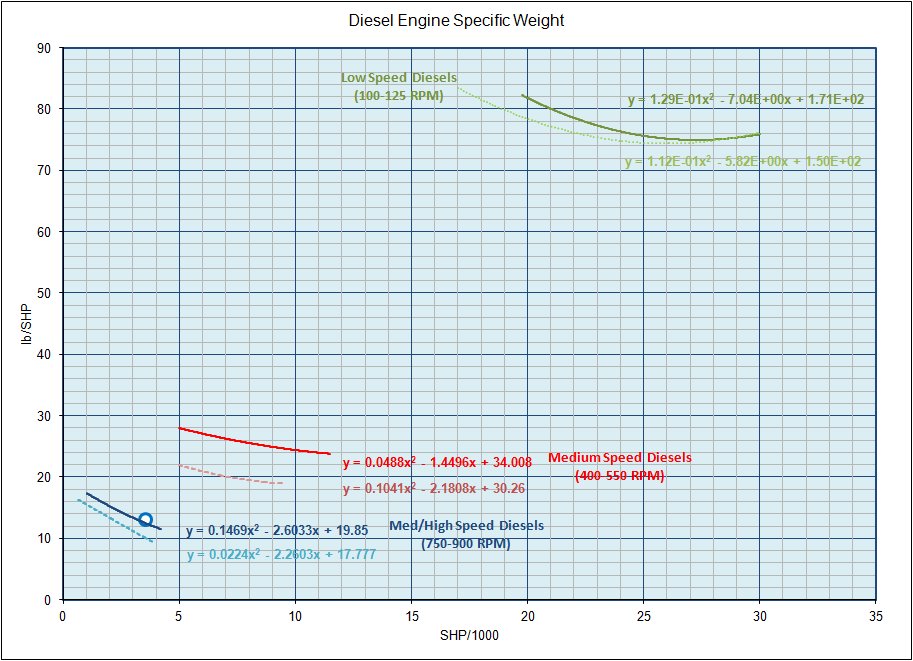
For Diesel engines here is a plot of specfic weight data for some typical diesel engines along with soe additional data points from other various sources. In this plot the engines are divided into three main groups as follows:
Low Speed Diesels - with an rpm in the range of 100-125
Medium Speed Diesels - with an rpm in the range of 400-550
Medium/High Speed Diesels - with an rpm in the range of 750-900
Medium Speed Diesels - with an rpm in the range of 400-550
Medium/High Speed Diesels - with an rpm in the range of 750-900
Transmission Systems
Currently this methodology only addresses mechanical (geared) transmission systems. In this methodology a ship's transmission system is assumed to consist of the reduction gears, the propulsion shafting, and the shaft bearings and thrust bearings. Eventually though I hope to expand this system to also include electrical transmission systems.
Reduction Gears
Typical marine reduction gears can be broken into single-reduction systems and double-reduction systems. As suggested by their names, a single-reduction system basically consists of one or more input pinions mated to a single reduction gear directly connected tothe propulsion shaft, while a double-reduction system will have one or more input pinions mated to high-speed gears which drive pinions that mate to a second stage reduction gear that directly drives the propulsion shaft.
[insert
image here]
An important parameter in reducition gear design is a term called the "K" Factor. In general the "K" factor is a measure of the tangential load on the gear's teeth divided by the face width of the gear adjusted by the pinion diameter and reduction ratio, as defined below:
K = Ft / ( b * d1 ) * ( R + 1 ) / R
Where:
Ft = Tangential Load in the Gear (@ the pitch circle)
b = the face width of the gear
d1 = the pinion diameter
R = gear ratio
b = the face width of the gear
d1 = the pinion diameter
R = gear ratio
By selecting "K" Factors for each stage of a reduction gear design, based on known "K" Factors for previous designs, and inputing other factors such as the input and output shaft speeds and input power, it is then possible make an estimate of the weight and size of a gear set for a new vessel.
To do this the following inputs should be defined:
- The Input Horsepower to the reduction gear
- The Input RPM to the reduction gear
- The "K" Factor of the High-speed Pinion
- The "K" Factor of the Low-Speed Pinion
- The RPM of the Output/Propeller shaft
A reduction gear can be designed either with or without a "locked train". In a "locked train" unit each high speed pinion meshes with two 1st stage reduction gears and thus transmit power to two 2nd stage reduction pinions, as shown in the figure below. In a gear set withiout a "locked train" the each high speed pinion drives a single 1st stage reduction gear, thus transmitting its power to a single 2nd stage pinion.
[insert
image here]
For a double-reduction gearset without a locked train the second stage reduction ratio (R2) is as follows:
R2 = sqrt ( Ninput / Nprop
) - 1
For a conventional gear system with a lock train the second stage reduction ratio (R2) is as follows:
R2 = sqrt ( Ninput / Nprop
) + 3
Where;
Ninput = the rpm of the diesel engine, gas
turbine, or steam turbine
And the first stage reduction ratio (R1) is:
R1 = Ninput / Nprop * R2
Sources such as the SNAME book "Marine Engineering" (edited by Roy Harrington) (Ref 200-3) suggest that based on good design practices effective face width should be in the range of 2.0 to 2.25 the pitch diameter of the pinion, or in other words:
b ~ 2.25 * d
Therefor, once these values are calculated it is then possible to determine the diameter of the 1st reduction pinion as follows:
d13 = 126,050 * HPinput
* (R + 1) / (Ninput * 2.25 * R * K )
Where, for a locked-train unit HPinput gets split
between the first two reduction pinions.
The diameter of the 1st reduction gear can thus be determined as:
D1 = R1 * d1
The diameter of the 2nd reduction pinion is then determined as:
d23 = 126,050 * HPinput
* (R + 1) / (Ninput * 2.25 * R * K )
Where;
Ninput = the rpm of the diesel engine, gas turbine, or steam
turbine divided by R1
Thus,
D2 = R2 * d2
Where D2 is the Bul Gear diameter
The weight of the total gear system can then be estimated as;
W = A ( Q / K ) n
Where;
Q = HP * ( R + 1 )3 / N * R1*
A = an empirical constant with a value of 12.95 suggested for conventional gears
n = an empirical constant between 0.8 to 1.0 for conventional gears
R1* = 2 * R1 for double reduction gears and R2* = R2
A = an empirical constant with a value of 12.95 suggested for conventional gears
n = an empirical constant between 0.8 to 1.0 for conventional gears
R1* = 2 * R1 for double reduction gears and R2* = R2
For a gearset with two inputs and a single output shaft the total weight would be;
Wtotal = 2 * W1 + W2
Shafting
.....
Shaft Bearings
In simple terms Ref 200-1 suggests that the weight of the shaft and thrust bearings are on the order of 15.0% the combined weight of the shafts and propellers.
Propulsors
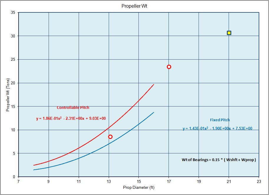
Currently, the methodology that I am considering assumes that a vessel will be outfitted with either Fixed Pitch or Controllable Pitch Propellers. For Nuclear plants, conventional 1200 psi steam plants and pressure-fired steam plants fixed pitch propellers would be suitable. For Diesel or Gas Turbine plants with either a reversing reduction gear, or a standard reduction gear and a clutch, fixed pitch propellers are also suitable. Finally, for a Diesel plant or Gas Turbine plant with a standard (non-reversing) reduction gear controllable pitch propellers would likely be most suitable.
The plot below gives a general estimate of both Fixed Pitch and Controllable Pitch propellers based on the diameter of the unit.
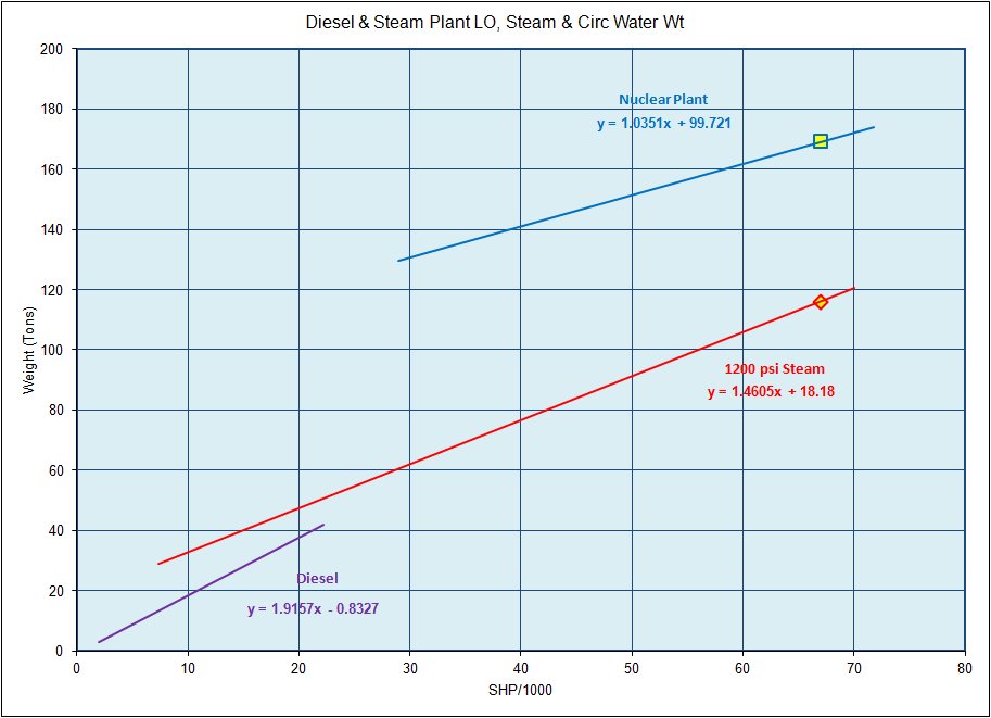
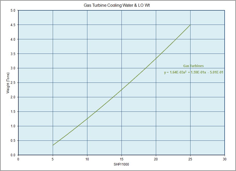
Other Components
For Diesel and Steam type plants this will include items such as controls, Lube Oil system, as well as the Steam piping and Circulating Water systems. For a Gas Turbine plant this will include primarily the controls, Lube Oil and Cooling Water Systems. The figures below show estimates of these weights for these type plants.