Landing Zone Layout
Currently,
the aircraft carrier design spreadsheet primarily focuses on CATOBAR
(or possibly STOBAR) vessels, and the layout of the Landing Zone on
these type vessels appears to play a significant role in the arrangment
of the ship's flgiht deck and overall size and configuarion of the
vessel.
Using the data from the Arrrestor Gear page the user has the opportunity to define the configuration of the "Landing Zone". Here the User is asked for input on the following items, also shown in the figure below;
The user is also asked for information on the largest aircraft carrier to be carried onboard the ship, including;
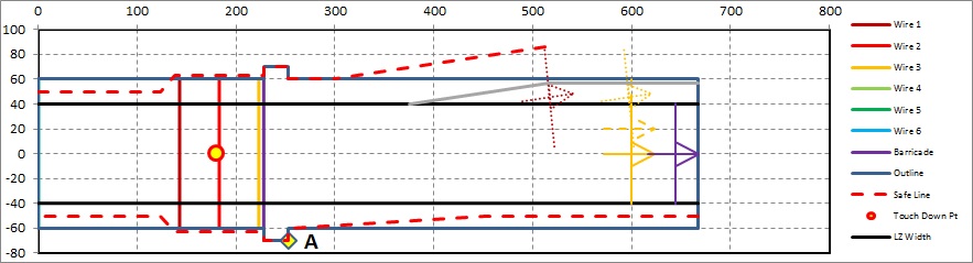
In the figure above,
Based on the above information and a couple other rules of thumb the
minimum landing zone width width has been set, as shown by the solid Black lines, a set of "safe parking" lines have been estimated as shown by the Red dashed lines, and a minimum extent of the starboard deck edge has also been determine, as shown by the solid Gray line.
In addition the total required length for the Landing Zone, the Landing Zone Width, and w100+ and w500+ weights are also calculated.
Using the data from the Arrrestor Gear page the user has the opportunity to define the configuration of the "Landing Zone". Here the User is asked for input on the following items, also shown in the figure below;
- the distance from the aft end of the Landing Zone to the
1st Arrestor Wire/Pendant. [With a Defualt value of 143ft
appearing to be typical, based on USN practice].
- the distance between the the 1st and 2nd wire, the 2nd and
3rd wire and so on up to a total of 6 possible wires, as well as the
type of arrestor gear used for each wire. (If less than 6 wires
are desred the user can ener "0" as required). [With a Default
value of 40ft appearing to be typical based on USN practice, though for
RN CVs from the 1950s and 1960s a value of 26ft appears typical for
those type vessels.]
- the distance from the last wire to the "barricade" and the
type of arrestor gear used for the barricade. [With a value of
5ft appearing ypical based on USN practice.]
- the type of arrestorr gear used as a spare (if
fitted). [Where it appears that it is typical for 1 additional
arrestor gear unit to be fitted as a spare.]
- the maximum pullout offset angle to port, used in defining
the 'safe parking' lines and minumum port side flight deck
geometry. [With a value of 7° to Port appearing typical based on
USN practice.]
- the length and offset distance of what I have termed as "ears" in way of the landing area which represent the additional deck area occupied by the barricade stanchions. This information is defined as Pt A in the figure below. [With a length of about 25ft and an offset of about 10ft appearing typical based on USN practice.]
The user is also asked for information on the largest aircraft carrier to be carried onboard the ship, including;
- the distance from the aircraft's nose gear to its extended
tailhook. [For the E-2A aircraft this information is listed as
51.3ft.]
- the distance from the aircraft's nose gear to its main gear. [For the E-2A aircraft this information is listed as 23.3ft.]
- the span of the aircraft's main gear. [For the E-2A aircraft this information is listed as 19.5ft.]
- and the desired turn around distance desired to be able to
attach tow gear and pull the aircraft clear of the landing zone.
[Where a distance of 39.0ft appears as being used in some reports that
I have read.]
In the figure above,
- The location of the target "Touch Down Pt" (as shown by the Yellow and Red dot)
- The arrestor wire/pendent and barricade locations and spacing (as shown by colored lines across the landing area)
- The maximum pullout distances and clearances for the largest aircraft carried (as identified colored overlayed Trangle and Cross shapes, which represent the wingspan, landing gear arrangement and tail hook location of the largest aircraft carried onboard in the following five conditions;
- At the maximum pullout of the Barricade along the centerline of the landing zone (as signified by the Purple Cross & Triangle shape)
- At the maximum pullout distance of the last arrestor wire pendent along the centerline of the landing zone (as signified by the solid Orange cross & triangle shape)
- At the maximum pullout distance of the last arrestor wire pendent for a plane that has landed 20ft off center to Starboard in the landing zone (as signified by the dashed Orange cross & triangle shape)
- At the maximum pullout distance of the last arrestor wire pendent for a plane that has landed at a 7° offset to Starboard in the landing zone (as signified by the dotted Orange cross & triangle shape)
- At the maximum pullout distance of the 1st arrestor wire pendent for a plane that has landed at a 7° offest to Starboard in the landing zone (as signified by the dotted Rust colored cross & triangle shape)
In addition the total required length for the Landing Zone, the Landing Zone Width, and w100+ and w500+ weights are also calculated.
This document maintained by PFJN@mnvdet.com.