Auxiliary Boiler System Weights
Over the years there have been proposals for incorporating auxiliary boiler systems onto non-steam propelled vessels to allow them to operate steam catapults, and as such I've tried to put together some infomration here to allow an individual to making an estimate of the weights of such systems. However, I should note that, whereas for other sections of this website and associated spreadsheet I have tried to base things off of existing vessels and systems, here I have had to make alot of assumptions on how I think an auxiliairy steam system might be configured since I could not find much information on any studies that may have been done in the past for programs such as the UK's CVF, the French PA-2, alternate concpets that may have been studied as part of the US CVX program or any of the studies down in the early to mid 1990's in Spain for small CATOBAR vessels.In order to try and estimate the weights and other design impacts of such an auxiliary steam system it is 1st necessary to try and better understand how steam catapults appear to work on a steam powered vessel and then try and assess what differences there may be on a non-steam powered vessel.
Basic Steam Plant Layouts
As shown in the figure below, in a conventional "fossil fueled" steamship, the energy needed to propel the vessel is stored within the fuel oil as "chemical energy". In order to make use of this "stored energy" the fuel is burned in a boiler where the heat given off due to its combustion gets transferred to "feedwater" (in the form of "thermal energy"), which results in the feedwater being converted into steam. This steam is then fed to the main propulsion turbines, where it is allowed to "expand", giving up much of the thermal energy it has in order to spin the turbine (resulting in the thermal energy being converted into mechanical/rotational work). The remaining low energy steam is then condensed back into feedwater in the ship's main condensors. This re-condensed steam is then repumped back to the boiler as feedwater.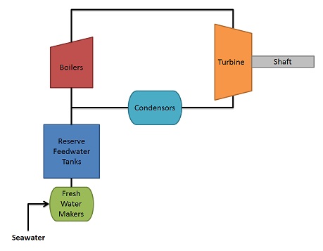
In such a system the feedwater/steam serves as a medium for transferring energy from the burning fuel to the mechanical components of the ship's drive train, and since the steam gets "re-condensed" for re-use it is considered a "closed" system (or a mostly "closed" system since there will be some losses along the way that will require the use of some make up feedwater to keep the system going).
Additionally, in practice relatively modern steam plants have also made use of components such as feedwater pre-heaters, steam superheaters, economizers and other such devices to help increase the overall plant efficiency.
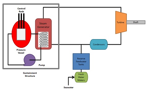
On nuclear powered vessels in place of the fossil-fuel fired boilers, a nuclear reactor is used, as shown in the figure below. Within the reactor the energy released due to the decay of radioactive materials is used to heat a coolant. This coolant in turn flows through a cycle where it is used as the "heating" element to convert feedwater to steam. This steam is then is used similarly to the steam described above for the simple fossil fuled plant.
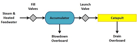
On both fossil fueled and nuclear powered vessels which use steam catapults, the steam needed for use in the catapults act as an "open" branch to the mostly "closed" loop main propulsion plant, in that the steam used by the catapults does not get recaptured and "re-condensed" for re-use as feedwater but is instead drained overboard, as shown in the figure below. As such new feedwater must be added back into the system to "make up" for the the steam used for the catapults. In general then, if I am remebering my electrical engineering correctly, the "steam accumulator" in such a systems kind of appears to serve a similar function as a "capacitor" in an electrical circuit, allowing a charge to be "built up" over a period of time and then be discharged rapidly.
Because the main propulsion turbines will likely be in use constantly on a steam powered vessel while it is underway, steam will likely always be being available onboard the ship for use by the catapults. Additionally, because the steam used by the catapults is only one part of the entire steam requirements on such a vessel, there will be a "degree of flexibility" in how the overall steam plant is able to handle the "variable loads" that operating steam catapults will likely impart on the overall system.
For a non-steam powered vessel fitted with steam catapults, an auxiliary boiler system will likely have specific requirements that need to be addressed. Specifically, such a plant will likely need to be able to produce enough steam within a given amount of time to meet the planned aircraft "sortie" requirements for the vessel, including both;
- providing enough steam to perform a single all "airwing" (or most of the "airwing") launch, as well as
- sustaining more limited operations throughout the day, such as maintaining a certain number of aircraft in the air for Combat Air Patrol and Airborne Early Warning purposes, while also being able to quickly accommodate the launch of standby aircraft as needed.
- the ability to
accommodate a high rate of steam generation for large scale launch operations, as well as the ability to
make up for a high rate of "steam loss" that this would impart on the system
- the ability to maintain periodic air operations throughout the day
- the
ability to provide a certain minimal amount of steam steam throughout
the day to ensure the ability to launch standby aircraft at a moments
notice
Initial Steam Plant Sizing
A first step in sizing of the boiler(s) for an auxiliary steam system would be to look at the known maximum energy output of the catapult (as noted in the Catapults & Ski Ramps page of this website) and the frequency with which the catapult would be required to exert this maximum energy. Data for the C13-2 Catapult from the Catapults & Ski Ramps page indicate that this unit is rated at a maximum launch energy of 75,000,000 ft-lb. Information from the internet (such as this page on the Federation of american Scientist website) suggests that a modern US CVN can launch aircraft at a rate of 1 every 20 seconds which would suggest a rate of 1 every 80 seconds per catapult for a ship with 4 catapults, though other anecdotal evidence from the internet suggest that not all 4 catapults are used as frequently as the others, and as such a higher rate per catapult may be possible.Using the 75,000,000 ft-lb and 1 launch every 80 seconds as a benchmark suggests that that at an assumed 100% efficiency an auxiliary steam plant on a non-steam powered vessel would have to be able to provide energy to the catapult's "accumulator" at a rate of 937,500 ft-lb/second (1,705 HP) to meet an 80 second launch cycle for a single C13-2 catapult.
Looking further at the C13-2 catapult data from Defense Industry Daily on the EMALS catapult system suggests that "Current steam catapults use about 615 kg/1350 pounds of steam per launch..." ( DID-EMALS ). Additionally, this document on a proposed internal combustion catapullt suggests a similar number of 1,320 pounds of feedwater per launch, specifically noting that the data is or the C13-2 catapult (but also appears to note the need for an additional 3% or so for catapult heating and/or steam smothering etc).
In addition, according to this document [add] the steam pressure required for a C13-2 catapult is 450 psig, which equates to a temperature of 460 oF for saturated steam. Based on steam tables for saturated steam (such as at this site) the enthalpy of saturated steam at 450 psig is about 1,205 BTU/lb. Since no condensate is recaptured into this system, if I am understanding correctly, the 1,350 lb * ( 1,205 ) BTU/lb = 1,626,750 BTU expended by the catapult launch. Using the same cycle time of one launch every 80 seconds for a single catapult would result in the need for the steam plant to provide 20,334 BTU/second which equates to 28,744 HP for a single C13-2 steam catapult. A value of 1,705 HP (as calculated previously for a 100% efficient system) divided by 28,744 HP suggests an actual efficiency of about 5.9%, which appears in line with a value of 4 to 6% efficiency for current steam catapult systems is stated in this document.
Additionally, 1350 lb over an 80 second period would equate to a notional steam flow rate of 60,750 lb/hr.
For other catapults, I would suspect a similar efficiency and thus an initial estimate of power requirements may be potentially estimated by taking the maximum launch energy and dividing by both the desired launch rate and an estimated efficiency of 5.9 to 6% or so.
Notional Stand Alone Auxiliary Steam Plant Layout
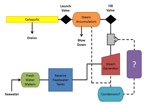
The figure below shows what I've been thinking about for a preliminary generic auxiliary steam plant layout for supporting steam catapults on a non-steam powered vessel. As shown in the figure there would be one or more fresh water maker(s), and tankage for storing make-up "feedwater" for the system. In addition there would then also be one or more "steam generators" (ie boilers) and "accumulators" for the catapults. Then, depending on the components used and the overall planned plant operation there may also likely be one or more "condensors" and feed pumps and possible feedwater pre-heaters, etc. And finally, if the plant is required to be able to perform an aircraft launch at almost any time, and due to the time it takes for typcial naval boilers to "start producing steam" it will likely be necessary for the auxiliary steam system to constantly produce steam at some minimal rate while the ship is "ready for operations", with the ability for the plant to quickly ramp up to a higher capacity. As such, if the plant is required to be producing steam (at some rate) even if air operations are not always underway then it may be desirable if that "unused" steam is put to some use in the mean time. Some thoughts here would be perhaps using this steam to run turbogenerators or perhaps freashwater makers.The image shown below demonstrates my thoughts on what such a system might look like, where the Purple box represents possible turbogenerators, freshwater makers or other such systems, if the steam also intended to be used for those purposes.
Based on discussions on the Warships1 Discussions Board, three potential concepts for "steam generators" were identified, as follows;
Each of these potential steam generating components have their own strengths and weaknesses which may have an impact on the overall configuration of the plant.
This document maintained by PFJN@mnvdet.com.